Campus LAN and Wireless LAN Solution Design Guide
Available Languages
Bias-Free Language
The documentation set for this product strives to use bias-free language. For the purposes of this documentation set, bias-free is defined as language that does not imply discrimination based on age, disability, gender, racial identity, ethnic identity, sexual orientation, socioeconomic status, and intersectionality. Exceptions may be present in the documentation due to language that is hardcoded in the user interfaces of the product software, language used based on RFP documentation, or language that is used by a referenced third-party product. Learn more about how Cisco is using Inclusive Language.
- US/Canada 800-553-2447
- Worldwide Support Phone Numbers
- All Tools
 Feedback
 Feedback
Definition and Introduction: Campus LAN and Wireless LAN
There is a tendency to discount the network as simple plumbing — to believe that the only design considerations are the size and the length of the pipes or the speeds and feeds of the links, and to dismiss the rest as unimportant. Just as the plumbing in a large stadium or a high-rise building is designed for scale, purpose, redundancy, protection from tampering or denial of operation, and the capacity to handle peak loads, the network requires similar consideration. As users depend on the network to access the most important information that they need to do their jobs and to transport their voice or video with reliability, the network must be able to provide resilient, intelligent transport. The reliable network design also needs to incorporate versatility in order to address the changing needs of an organization.
Here are some key concepts that you should address when creating a reliable and versatile network design. The network should be:
● Always on and resilient—Continuously on and available.
● Intelligent—Adapting to changing needs, beyond the limits of basic standards, using insight into network activity.
● Secure—Protecting the organization and its users.
Planning for the Future
As you look at a network design, consider the networking trends and future needs of an organization.
● The network must be ready to appropriately scale over time in order to meet the demands of the organization it is supporting.
● Because demands on wireless access points (APs) with the latest standards, including Wi-Fi 6 (802.11ax) technology exceed 1 Gbps, and the IEEE has ratified the 802.3bz standard that defines 2.5 Gbps and 5 Gbps Ethernet, you should deploy a network that is ready to support the demand without requiring an upgrade of the existing copper Ethernet wiring plant. You accommodate these latest demands by deploying network platforms including Cisco® Catalyst Multigigabit technology.
● As you deploy new devices with higher power requirements, such as lighting, surveillance cameras, virtual desktop terminals, remote access switches, and APs, your design should have the ability to support power over Ethernet up to 90W per port, offered with Cisco Universal Power Over Ethernet Plus, and the access layer should also provide PoE perpetual power during switch upgrade and reboot events. The Cisco Catalyst 9000 Series access layer switches are perpetual PoE-capable and ready for 100W per port, as that technology becomes available.
● Compliance issues drive a choice of platforms required when you support standards certifications and MACsec. For those cases, you should also be prepared to make analytic data available, using technologies such as NetFlow.
● The Internet of Things (IoT) impacts today's network design. Your network should support TrustSec and other segmentation and virtualization technologies, such as Cisco Software-Defined Access (SD-Access) in order to enable the scale and expanded uses and policies for the network driven by these trends.
● Bandwidth needs are doubling potentially multiple times over the lifetime of a network so that the network deployed today needs to be prepared to aggregate using 10 Gbps Ethernet to 25 Gbps to 40 Gbps to 100 Gbps capacities or more over time.
● The network platforms deployed today should offer the best longevity into the future, versus selecting the equipment that only meets the limits of today's needs.
● To reduce operational complexity, you can use a centralized controller with open APIs, allowing for very fast, lower-risk deployment of network devices and services through UI and existing orchestration systems—Cisco Digital Network Architecture Center (Cisco DNA Center) automates this network device configuration and management to achieve your organization's intent.
Cisco Digital Network Architecture (Cisco DNA)
Cisco Digital Network Architecture (Cisco DNA) provides a roadmap to digitization and a path to realize immediate benefits of network automation, assurance, and security. The campus local area network (LAN) is the network that supports devices people use within a location to connect to information. The use of the word campus does not imply any specific geographic size or organizational boundary—the campus LAN can range in size from a single switch at a small remote site up to a large multi-building infrastructure, supporting classrooms, carpeted office space, and similar places where people use their devices for their daily activities. The campus design incorporates both wired LAN and wireless LAN connectivity for a complete network access solution. This guide explains:
● The design of the campus wired LAN foundation.
● How the WLAN extends secure network access or is exclusive network access for your mobile workforce.
● How the WLAN can provide guest access for contractors and visitors to your facilities.
If you didn’t download this guide from Cisco Community or Design Zone, you can check for the latest version of this guide.
Find related deployment guides, design guides, and white papers, at the following pages:
● https://www.cisco.com/go/designzone
Design: Campus LAN and Wireless LAN
Designing a LAN for the campus use case is not a one-design-fits-all proposition. The scale of campus LAN can be as simple as a single switch and wireless AP at a small remote site or a large, distributed, multi-building complex with high-density wired port and wireless requirements. The deployment may require very high availability for the services offered by the network, with a low tolerance for risk, or there may be tolerance for fix-on-failure approach with extended service outages for a limited number of users considered acceptable. Platform choices for these deployments are often driven by needs for network capacity, the device and network capabilities offered, and the need to meet any compliance requirements that are important to the organization.
● Traditional Access- Dedicated Distribution and Access Layers (L2 or L3). You impose most of the campus wired LAN design complexity when aggregating groups of access switches by interconnecting the access layers to the distribution layers. If devices connecting to the access layer have a requirement to communicate with a Layer 2 logical adjacency and those connections cover multiple physical wiring closets connected to a distribution layer, then it is possible to adapt the traditional multilayer campus design to address the Layer 2 adjacency needs. However, the traditional designs drive more complex configurations with additional protocols that must be kept consistent across multiple devices.
● Simplified Access –Virtualized StackWise Access & StackWise Virtual Distribution. To improve the design, there are preferred alternatives that make the deployment easier to manage and less prone to mistakes, while enhancing overall network performance. Such alternatives include the simplified distribution layer using options such as a switch stack or a StackWise Virtual system, and the simplified access layer using a switch stack with StackWise technology. Both make deployment and troubleshooting much easier for support staff.
● Cisco Software Defined Access – Campus Fabric and Automation of the Distribution & Access Layers. A design alternative is available for organizations that either don't have the need to extend Layer 2 connectivity across an access-to-aggregation boundary or have other means of implementing this functionality, such as when using fabric technology for campus designs—an integral part of Cisco SD-Access. The alternative to the Layer 2 designs is to extend Layer 3 connectivity to the access layer. The implementation of a well-designed Layer 3 access network ensures consistent, configuration, performance, scalability, and high availability of the network versus the traditional multilayer campus design.
The motivation for the recommended design choices is not that they are the only options available but that the recommendations highlight preferred choices given the scope of the requirements. Even though the traditional multilayer campus design previously mentioned is a widely deployed, valid design choice, the design is not one that is typically recommended considering better alternatives that are currently available.
When you integrate the wireless components of the campus design with the wired components, the design can often be treated as an overlay that is dependent upon the services provided by the underlying campus infrastructure. This is especially evident for larger networks, because increasing capacity with dedicated devices becomes a requirement. Smaller networks, such as those at small remote sites, offer opportunities for simplification and optimization that are also reflected in the design choices shown below.
The primary design options are grouped by scale, and then appropriate selections are based on the capabilities desired. The selection from the spectrum of capabilities is based on the needs of a specific deployment.
Design Fundamentals: Campus Wired LAN
The LAN is the networking infrastructure that provides access to network communication services and resources for end users and devices spread over a single floor or building. You create a campus network by interconnecting a group of LANs that are spread over a local geographic area. Campus network design concepts include small networks that use a single LAN switch, up to very large networks with thousands of connections.
The campus wired LAN enables communications between devices in a building or group of buildings, as well as interconnection to the WAN and Internet edge at the network core.
Specifically, this design provides a network foundation and services that enable:
● Tiered LAN connectivity.
● Wired network access for employees.
● IP Multicast for efficient data distribution.
● Wired infrastructure ready for multimedia services.
Hierarchical design model
The campus wired LAN uses a hierarchical design model to break the design up into modular groups or layers. Breaking the design up into layers allows each layer to implement specific functions, which simplifies the network design and therefore the deployment and management of the network.
Modularity in network design allows you to create design elements that can be replicated throughout the network. Replication provides an easy way to scale the network as well as a consistent deployment method.
In flat or meshed network architectures, changes tend to affect a large number of systems. Hierarchical design helps constrain operational changes to a subset of the network, which makes it easy to manage as well as improve resiliency.
Modular structuring of the network into small, easy-to-understand elements also facilitates resiliency via improved fault isolation.
A hierarchical LAN design includes the following three layers:
● Access layer—Provides endpoints and users direct access to the network
● Distribution layer—Aggregates access layers and provides connectivity to services
● Core layer—Provides connectivity between distribution layers for large LAN environments
Each layer —access, distribution, and core— provides different functionality and capability to the network. Depending on the characteristics of the deployment site, you might need one, two, or all three of the layers. For example, a site that occupies a single building might only require the access and distribution layers, while a campus of multiple buildings will most likely require all three layers.
Regardless of how many layers are implemented at a location, the modularity of this design ensures that each layer will provide the same services, and in this architecture, will use the same design methods.
Access layer
The access layer is where user-controlled devices, user-accessible devices, and other end-point devices are connected to the network. The access layer provides both wired and wireless connectivity and contains features and services that ensure security and resiliency for the entire network.
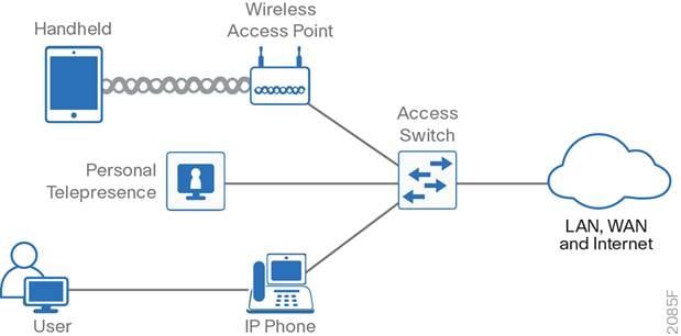
● Device connectivity—The access layer provides high-bandwidth device connectivity. To help make the network a transparent part of an end-user's day-to-day job, the access layer must support bursts of high-bandwidth traffic when users perform routine tasks, such as sending large emails or opening a file from an internal web page.
Because many types of end-user devices connect at the access layer —personal computers, IP phones, wireless APs, and IP video surveillance cameras— the access layer can support many logical networks, delivering benefits for performance, management, and security.
● Resiliency and security services—The access-layer design must ensure that the network is available for all users who need it, whenever they need it. As the connection point between the network and client devices, the access layer must help protect the network from human error and from malicious attacks. This protection includes ensuring that users have access only to authorized services, preventing end-user devices from taking over the role of other devices on the network, and, when possible, verifying that each end-user device is allowed on the network.
● Advanced technology capabilities—The access layer provides a set of network services that support advanced technologies, such as voice and video. The access layer must provide specialized access for devices using advanced technologies, to ensure that traffic from these devices is not impaired by traffic from other devices and to ensure efficient delivery of traffic that is needed by many devices in the network.
Multigigabit Ethernet (mGig) and PoE at the access-layer
As customers migrate to 802.11ax (Wi-Fi 6), the access layer switch platforms to which the Catalyst 9100 Series APs connect may also need to be upgraded. Data rates above 1 Gbps, supported by 802.11ax (Wi-Fi 6) APs, are driving the requirement for mGig port speeds (2.5 Gbps and 5 Gbps) at the access layer. The higher MIMO rates of these APs, along with the rapid adoption of IoT devices is also driving the requirement for higher PoE requirements (PoE+, Cisco UPOE / 802.3bt Type 3, and Cisco UPOE+ / 802.3bt Type 4) at the access layer switch ports.
Oversubscription ratios
The migration to mGig may also require increasing uplink port speeds in order to maintain the desired oversubscription ratio. Determining the oversubscription ratio of the uplink when deploying mGig technology can be more challenging than traditional switches with only 1 Gbps ports. You need to take into consideration the number of access ports on the switch which support mGig, since not all switches support mGig on all ports. You also need to take into consideration the speeds at which the mGig port is capable of operating, as well as the speed at which the port will be operating. Although an mGig switch port may be capable of operating at 10 Gbps, Cisco Catalyst 9100 Series APs only operate at mGig speeds up to 5 Gbps currently.
For example, let’s say you deploy a 48-port switch which supports mGig up to 10 Gbps on 12 access ports, 1 Gbps on the other 36 ports, and with 4x10 Gbps fixed uplinks. However, you only provision two 10 Gbps uplinks. This configuration would provide up to 20 Gbps uplink bandwidth, assuming all uplinks are active – as in a Multichassis EtherChannel (MEC) configuration.
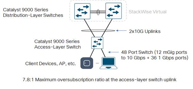
The maximum potential bandwidth usage of the switch ports would be 12 x 10 Gbps = 120 Gbps plus 36 x 1Gbps = 36 Gbps, for a total 156 Gbps. The maximum uplink oversubscription ratio would be 156 Gbps : 20 Gbps or 7.8:1, assuming all mGig ports were operating at 10 Gbps.
More realistically, you may have the following actually connected to the switch:
● 8 Catalyst 9100 Series APs operating at 5 Gbps connected to the switch ports
● 32 Cisco IP Phones and/or end-user devices (PCs, Mac’s etc.) operating at 1 Gbps connected to the switch ports
● 8 Unused ports for future expansion and capacity
The actual potential bandwidth usage of the switch ports would be 8 x 5 Gbps = 40 Gbps plus 32 x 1 Gbps = 32 Gbps, for a total 72 Gbps. Therefore a more realistic view of the oversubscription ratio is 72 Gbps : 20 Gbps, or 3.6:1.
This configuration provides for additional capacity, in that you have an additional 2 x 10 Gbps unused uplinks as additional devices require mGig port speeds, as devices transition to 10 Gbps speeds, and as you expand capacity in a switch stack configuration
Switch stack configurations
Migrating to a switch stack is an effective, flexible, and scalable solution to expand network capacity at the access-layer. The benefits of a switch stack are as follows:
● The switch stack behaves as a single device (characteristics and functionality of a single switch)
● The switch stack allows expansion of switch ports without having to manage multiple devices
● Switches can be added or removed from the switch stack without affecting the overall operation of the switch stack
● Depending upon the configuration of the switch stack, it can continue to transmit data even if a link or switch within the stack fails
When adding additional access layer switches in a stackable configuration, you should design the switch stack with the desired oversubscription ratio both during normal operations, and if there is a failure of a switch within the stack.
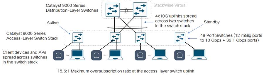
For example, let’s say you deploy four 48-port switches each of which supports mGig up to 10 Gbps on 12 access ports, 1 Gbps on the other 36 ports, with fixed 4x10 Gbps uplink ports. However, you decide to use only four 10 Gbps uplinks spread across two switches in the stack. This configuration would provide up to 40 Gbps uplink bandwidth in a MEC configuration, when both switches are operational. However, you now have 192 access ports.
The maximum potential bandwidth usage of the switch ports would be 48 x 10 Gbps = 480 Gbps plus 144 x 1 Gbps = 144 Gbps, for a total 624 Gbps. The maximum uplink oversubscription ratio would be 624 : 40 or 15.6:1 assuming all mGig ports were operating at 10 Gbps and all the 1 Gbps ports were being used.
More realistically, you may have the following actually connected to the switch:
● 32 Catalyst 9100 Series APs operating at 5 Gbps connected across the switch stack
● 128 Cisco IP Phones and/or end-user devices (PCs, Mac’s etc.) operating at 1 Gbps connected across the switch stack
● 32 unused ports across the switch stack for future capacity
The actual potential bandwidth usage of the switch ports would be 32 x 5 Gbps = 160 Gbps plus 128 x 1 Gbps = 128 Gbps, for a total 288 Gbps. Therefore a more realistic view of the oversubscription ratio is 288 Gbps : 40 Gbps, or 7.2:1.
Again, this configuration provides for additional capacity, in that you have an additional 12 x 10 Gbps unused uplinks across the switch stack, as additional devices require mGig port speeds, as devices transition to 10 Gbps speeds, and as you add additional switches in the switch stack.
If one of the switches with uplinks were to fail, the number of uplinks decreases to 2 x 10 Gbps. However, the number of ports also decreases by 48 switch ports. In this scenario, it is important to balance the devices (operating at mGig speeds and at 1 Gbps speeds) across all switches to maintain a similar oversubscription ratio. For example, APs operating at 5 Gbps should be spread equally across the switches in the stack. This is already a best practice for AP high availability in a wireless deployment. Assuming all devices were equally distributed across the four switches in the example above, if one of the switches with uplinks were to fail, the actual oversubscription ratio would increase from approximately 7:2:1 to 10.8:1.
Another best practice is to select switches without uplinks as the active and standby of the switch stack, as shown in the figure above. Uplinks should be provisioned on the member switches. This way, if the active switch of the stack fails, you don’t have a double failure – meaning that you lose both the active switch and half of your uplinks.
Modular access layer switch platforms
An alternative to deploying switch stacks at the access layer is to deploy modular switch platforms, such as the Catalyst 9400 Series. Catalyst 9400 Series 4, 7, or 10-slot models can be deployed, depending upon the port density requirements of your floor IDFs (wiring closets).
An advantage of modular platforms is that additional linecards can be added to empty slots within the chassis to increase capacity, without having to worry about whether additional rack space or power (assuming sufficient power supplies are already provisioned within the chassis) exists within the IDF which houses the modular switch. Adding an additional linecard may also be less expensive than purchasing another stackable or standalone switch.
Another advantage of modular platforms is that they are typically designed such that the supervisor can be upgraded to increase the performance of the platform, without having to replace it. This can be a cost advantage of modular platforms over time, compared to stackable platforms. Redundant supervisors can be deployed to provide chassis-level high availability such as Non-Stop Forwarding (NSF) and Stateful Switchover (SSO) – similar to the active / standby functionality with NSF / SSO of a switch stack.
As with switch stacks, uplinks should be spread across linecards within the modular chassis. Oversubscription ratios should be determined both during normal operations and during failure scenarios. APs and end-user devices should be spread across available linecards to minimize the impact of the failure a single linecard within a modular chassis.
Increasing uplink speeds
As you continue to add more switches to a switch stack you must keep in mind the distribution of the uplinks across the switches in the switch stack, and the oversubscription ratio during failure scenarios. Likewise, as you continue to add more linecards to a modular switch platform, you must keep in mind the distribution of the uplinks across the linecards, and the oversubscription ratio during linecard failure scenarios.
Deploying multiple 10 Gbps uplinks may not be effective for larger switch stacks or modular platforms when migrating to mGig capable switches or linecards. The maximum number of links in an EtherChannel configuration is eight, resulting in a maximum uplink bandwidth of 80 Gbps. Further, this requires eight 10 Gbps switch ports across the distribution layer switches, for each access layer switch or switch stack.
Hence, it may be more optimal to migrate to higher speed uplinks between the access layer switch or switch stack and the distribution layer switches.
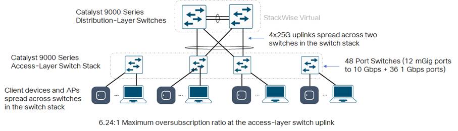
For example, instead of deploying four 48-port switches with fixed 4 x 10 Gbps uplinks in a switch stack configuration, you may want to deploy four 48-port switches along with a 2 x 25 Gbps uplink module in two of the switches within the stack.
This configuration provides up to 100 Gbps uplink bandwidth in a MEC configuration, when both switches with uplinks are operational. Fewer uplink ports are required at the distribution layer StackWise Virtual pair, and fewer optical fiber pairs are needed between the distribution layer StackWise Virtual pair and each of the access layer switch stacks. However, when deciding to upgrade the uplink speeds between the access and distribution-layer switches, you should keep in mind the following:
● The optical transceiver modules which connect the distribution layer switches to the access layer switch platforms have to interoperate with each other and have to be compatible with the fiber optic building distribution cabling – multimode fiber (MMF) or single mode fiber (SMF).
Note: Cisco offers a gradual migration path with the support of dual-rate optics, where the same 25 Gbps optics can operate at both 10 Gbps and 25 Gbps speeds. With this approach, distribution layer devices can be upgraded to 25 Gbps while the access layer still operates at 10 Gbps, and the access layer switches can be upgraded over a period of time.
● If you have older multimode fiber (OM1), speeds above 10 Gbps may not be supported.
Single mode fiber generally supports both higher transmission rates and longer distances than multimode fiber.
Uplink queuing
The actual uplink oversubscription ratio that you implement between your access and distribution layer switches is dependent upon your business requirements. Uplink ratios up to 20:1 between the access and distribution layer switches, and 4:1 between the distribution layer and core switches have been implemented in networks. The higher the oversubscription ratio, the higher the probability that temporary or transient congestion of the uplink may occur if multiple devices transmit or receive simultaneously.
Catalyst 9000 Series switches dynamically allocate buffer space across switch ports and queues in order to optimize the utilization of the existing buffer space. However, switch buffer space is a finite quantity that depends on the model of the Catalyst 9000 Series switch platform (specifically the version of the UADP ASIC and the number of UADP ASICS within the switch platform). During periods of temporary congestion the buffers on individual switch ports and queues may become exhausted, resulting in packet loss.
It is recommended to implement queuing on switches, where oversubscription of ports can result in transient congestion, which can cause packet loss. Queuing ensures that when congestion occurs, your higher priority traffic which is more susceptible to packet loss – such as voice traffic – is given preferential treatment over lower priority traffic. This preserves the quality of experience for your business critical applications, such as voice.
Access layer variations
In some situations, such as for IoT and for multi-dwelling unit (MDU) deployments, the access layer is often augmented with additional cascaded switches. For Cisco Software-Defined Access (described later) access extension deployments these access devices may be extended node switches. For MDU deployments the devices may be small distributed access switches or gigabit passive optical network (GPON) optical network termination devices. Network designs for these and other variations of the access layer are outside the scope of this guide.
Access layer platforms
The preferred options for the campus wired LAN include the following Cisco switches as platforms for the access layer:
● Cisco Catalyst 9400 Series Switches (modular chassis)
● Cisco Catalyst 9300 and 9300-L Series Switches
● Cisco Catalyst 9200 and 9200-L Series Switches
Distribution layer
The distribution layer supports many important services. In a network where connectivity needs to traverse the LAN end-to-end, whether between different access layer devices or from an access layer device to the WAN, the distribution layer facilitates this connectivity.
● Scalability—At any site with more than two or three access-layer devices, it is impractical to interconnect all access switches. The distribution layer serves as an aggregation point for multiple access-layer switches.
The distribution layer can lower operating costs by making the network more efficient, by requiring less memory, by creating fault domains that compartmentalize failures or network changes, and by processing resources for devices elsewhere in the network. The distribution layer also increases network availability by containing failures to smaller domains.
● Reduce complexity and increase resiliency—The campus wired LAN has the option to use a simplified distribution layer, in which a distribution-layer node consists of a single logical entity that can be implemented using a pair of physically separate switches operating as one device (StackWise Virtual) or using a physical stack of switches operating as one device. Resiliency is provided by physically redundant components like power supplies, supervisors, and modules, as well as stateful switchover to redundant logical control planes.
This approach reduces complexity of configuring and operating the distribution layer because fewer protocols are required. Little or no tuning is needed to provide near-second or sub-second convergence around failures or disruptions.
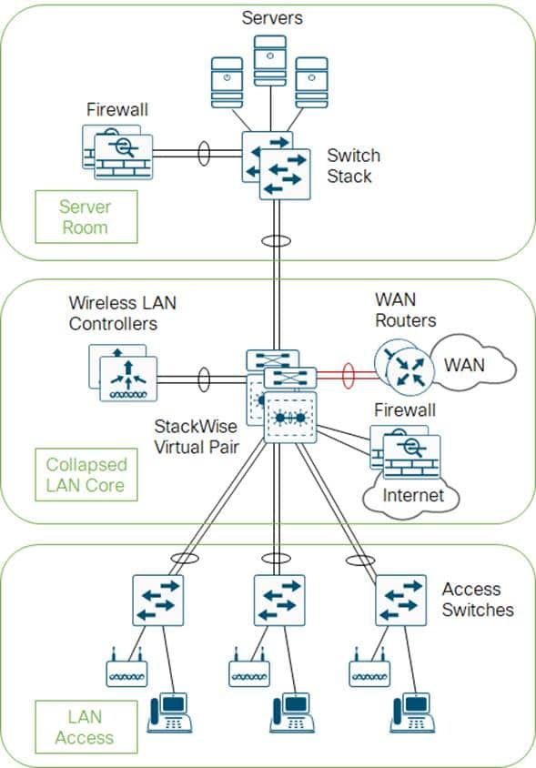
Two-tier design
The distribution layer provides connectivity to network-based services, to the WAN, and to the Internet edge. Network-based services can include and are not limited to Wide Area Application Services (WAAS) and WLAN controllers. Depending on the size of the LAN, these services and the interconnection to the WAN and Internet edge may reside on a distribution layer switch that also aggregates the LAN access-layer connectivity. This is also referred to as a collapsed core design because the distribution serves as the Layer 3 aggregation layer for all devices.
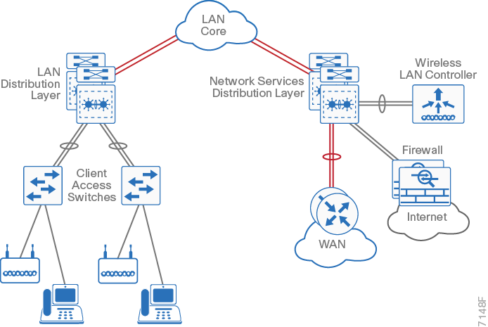
Three-tier design
Larger LAN designs require a dedicated distribution layer for network-based services versus sharing connectivity with access layer devices. As the density of WAN routers, WAAS controllers, Internet edge devices, and WLAN controllers grows, the ability to connect to a single distribution layer switch becomes hard to manage. When connecting at least three distributions together, using a core layer for distribution connectivity should be a consideration.
There are several factors that drive LAN design with multiple distribution layer modules:
● The number of ports and port bandwidth that the distribution layer platform can provide affects network performance and throughput.
● Network resilience is a factor when all LAN and network-based services rely on a single platform, regardless of that platform's design, it can present a single point of failure or an unacceptably large failure domain.
● Change control and frequency affects resilience. When all LAN, WAN, and other network services are consolidated on a single distribution layer, operational or configuration errors can affect all network operation.
● Geographic dispersion of the LAN access switches across many buildings in a larger campus facility would require more fiber optic interconnects back to a single collapsed core.
Like the access layer, the distribution layer also provides quality of service (QoS) for application flows to guarantee critical applications and multimedia applications perform as designed.
Distribution layer platforms
The preferred Cisco switches for deploying the distribution layer of the campus wired LAN include:
● Cisco Catalyst 9600 Series Switches (modular chassis)
● Cisco Catalyst 9500 Series Switches
● Cisco Catalyst 9400 Series Switches (modular chassis)
Core layer
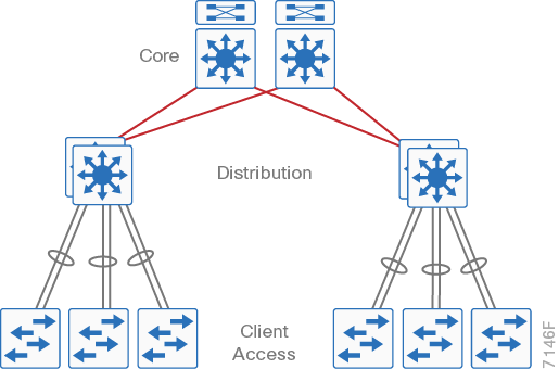
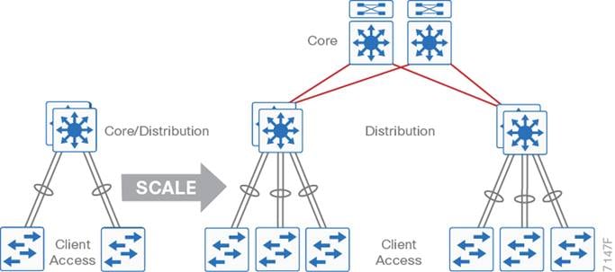
In a large LAN environment, there often arises a need to have multiple distribution layer switches. One reason for this is that when access layer switches are located in multiple geographically dispersed buildings, you can save potential costly fiber-optic runs between buildings by locating a distribution layer switch in each of those buildings. As networks grow beyond three distribution layers in a single location, organizations should use a core layer to optimize the design.
Another reason to use multiple distribution layer switches is when the number of access layer switches connecting to a single distribution layer exceeds the performance goals of the network designer. In a modular and scalable design, you can collocate distribution layers for data center, WAN connectivity, or Internet edge services.
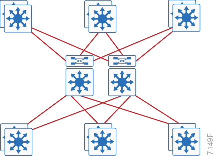
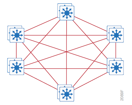
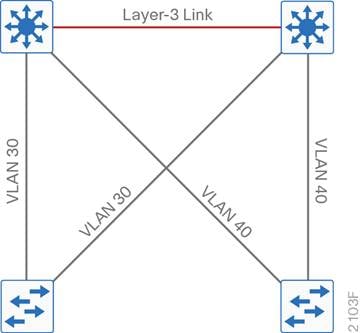
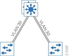
In environments where multiple distribution layer switches exist in close proximity and where fiber optics provide the ability for high-bandwidth interconnectivity, a core layer reduces the network complexity to N * 2 redundant links for N distributions, down from N * (N-1) / 2 redundant links, as shown in the following two figures.
The core layer of the LAN is a critical part of the scalable network and, by design, is one of the simplest. The distribution layer provides the fault and control domains, and the core represents the 24x7x365 non-stop connectivity between them, which organizations must have in the modern business environment where connectivity to resources to conduct business is critical. Connectivity to and from the core is Layer 3–only, which drives increased resiliency and stability.
Oversubscription ratios
For three-tiered designs, increasing the uplink speeds between the access and distribution layer switches may also require increasing uplink speeds between the distribution and core layer switches in order to maintain the desired oversubscription ratio.
Determining the oversubscription ratio of the uplink between the distribution and core layer switches is fairly straight forward. You need to take into consideration the number of ports connecting the distribution layer switches to the access layer switches or switch stacks, as well as the speeds at which the ports are operating.

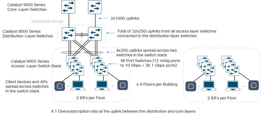
For example, let’s say your distribution layer switch is a StackWise Virtual pair that supports a building with 4 floors. Each floor has two IDFs (wiring closets). Each IDF has an access layer switch stack consisting of four 48-port switches along with a 2 x 25 Gbps uplink module in two of the switches within the stack. The total number of 25 Gbps ports required at the distribution layer switches is 4 uplinks x 2 IDFs per floor x 4 floors = 32 ports.
This configuration would provide up to 32 x 25 Gbps = 800 Gbps bandwidth between the distribution layer and access layer switches. Simply keeping existing 2 x 40 Gbps uplinks would only provide up to 80 Gbps between the distribution layer and core layer switches. This would provide an oversubscription ratio of 800:80 or 10:1 between the distribution and core layers. Depending upon your business requirements, this may be insufficient.
Increasing Uplink Speeds
You could choose to add additional 40 Gbps links between the distribution and core layer switches, possibly operating in a Layer 3 EtherChannel configuration. However, this would require additional 40 Gbps switch ports at every distribution layer and core layer switch. More importantly, it would require additional fiber optic pairs between the distribution layer switches and the core layer switches.
In a large campus deployment, the core layer switches may be located in a centralized data center in a different building. If insufficient optical pairs exist, then additional optical cabling would need to be pulled between the centralized data center and each of the buildings. This could be a very expensive proposition, as existing conduit space between the buildings may not be capable of supporting additional cabling, and you run the risk of damaging the existing cabling in the conduit – resulting in an extended outage. Installing new conduit may involve getting the necessary right-of-way to trench and install underground conduit – on top of the cost to install the new fiber optic cable.
An alternative may be to upgrade the uplink speeds between the distribution layer and core layer switches to 100 Gbps.
This would provide an oversubscription ratio of 800:200 or 4:1 between the distribution and core layers.
As with the access layer, when deciding to upgrade the uplink speeds between the distribution layer switches and the core layer switches, you should keep in mind the following:
● The optical transceiver modules which connect the distribution layer switches to the core layer switch platforms have to interoperate with each other and have to be compatible with the fiber optic cabling between buildings.
Due to the increased distances between buildings, single mode fiber (SMF) may already be installed between the distribution and core layer switches. This may help facilitate the migration from 40 Gbps to 100 Gbps between the distribution and core layers.
Core layer platforms
The preferred Cisco switches used as campus platforms for the core layer are:
● Cisco Catalyst 9600 Series Switches (modular chassis)
● Cisco Catalyst 9500 Series Switches
The capacity, density, and features are the primary differences driving platform selection. Both lead platforms have sibling platforms that may be appropriate for the core role in existing networks or networks where the full capabilities of the lead platforms are not required.
Design Options: Campus Wired LAN
When you scale from a single switch in a campus LAN up to a full three-tier campus network, the reliability of the network is increasingly important, because network downtime likely affects a greater user population with a larger workplace and economic significance. To mitigate the concerns about unavailability of network resources, campus designs include additional resiliency options, such as redundant links, switches, and switch components. In traditional multilayer campus designs, the added resiliency comes at a cost of configuration complexity, with most of the complexity introduced from the interaction of the access and aggregation layers of the campus LAN.
The primary function of the distribution layer is to aggregate access layer switches in a given building or campus. The distribution layer provides a boundary between the Layer 2 domain of the access layer and the Layer 3 domain that provides a path to the rest of the network. This boundary provides two key functions for the LAN. On the Layer 2 side, the distribution layer creates a boundary for spanning tree protocol (STP), limiting propagation of Layer 2 faults. On the Layer 3 side, the distribution layer provides a logical point to summarize IP routing information when it enters the network. The summarization reduces IP route tables for easier troubleshooting and reduces protocol overhead for faster recovery from failures.
Layer 2 access with traditional multilayer campus design
Traditional LAN designs use a multi-tier approach with Layer 2 from the access layer to the distribution layer, where the Layer 3 boundary exists. The connectivity from the access layer to the distribution layer can result in either a loop-free or looped design.
In the traditional network design, the distribution layer has a pair of standalone switches for resiliency. It is recommended that you restrict a Layer 2 virtual LAN (VLAN) to a single wiring closet or access uplink pair in order to reduce or eliminate topology loops that STP must block and that are a common point of failure in LANs. Restricting a VLAN to a single switch provides a loop-free design, but it does limit network flexibility.
To create a resilient IP gateway for VLANs in the traditional design, you must use first-hop redundancy protocols (FHRP), which provide hosts with a consistent MAC address and gateway IP for a VLAN. Hot standby routing protocol (HSRP) and virtual router redundancy protocol (VRRP) are the most common gateway redundancy protocols, but they only allow hosts to send data out one of the access uplinks to the distribution layer and require additional configuration for each aggregation switch in order to allow you to distribute VLANs across uplinks. Gateway load-balancing protocol (GLBP) does provide greater uplink utilization for traffic exiting the access layer by balancing load from hosts across multiple uplinks, but you can only use it in a non-looped topology.
Note: All FHRP protocols require that you fine-tune the default timer settings in order to allow for sub-second network convergence, which can impact switch CPU resources.
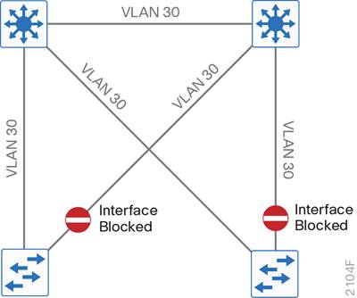
Some organizations require the same Layer 2 VLAN be extended to multiple access layer closets to accommodate an application or service. The looped design causes spanning tree to block links, which reduces the bandwidth from the rest of the network and can cause slower network convergence. The inefficiencies and the increased potential for misconfiguration drive network engineers to look for more appealing alternatives.
The following is a summary of some of design and operational concerns with the traditional multilayer campus design, driving alternative approaches:
● Spanning-tree protocol looping behavior, including blocked links, slow convergence, asymmetric forwarding, and switch CAM and ARP table tuning to address unicast flooding
● FHRP configuration consistency, slow convergence times driving protocol tuning in conflict with non-stop forwarding systems
● Layer 3 protocol tuning and protocol-dependent scale and recovery, multicast protocol configuration consistency and tuning, and general control plane, management, and forwarding complexity
Note: The Flexlink+ feature of enables the user to configure a pair of a Layer 2 interfaces (trunk ports or port channels) where one interface is configured to act as a backup to the other. The feature provides an alternative solution to the Spanning Tree Protocol (STP).
Because of the design and operational concerns inherent in the traditional multilayer campus design, organizations strive to deploy different designs, whenever possible.
Layer 3 routed access campus design
In another approach to access and distribution layer design, you can use Layer 3 beyond just the core and distribution layers and configure Layer 3 all the way into the access layer. Using the Layer 3 access design removes the Layer 2-to-Layer 3 boundary at the distribution layer, and makes each access switch the boundary between the Layer 2 access ports and outbound Layer 3 connectivity. The benefits of this design are that you eliminate spanning tree loops and reduce protocols because the IP gateway is now the access switch. Because there are no spanning-tree blocking links, you can use both uplinks to the access layer and increase effective bandwidth available to the users. This design makes it easy to maintain configuration consistency, while providing excellent convergence properties with minimal tuning, as the more complex Layer 2 interaction at the Layer 3 distribution is eliminated.

The challenges with the routed access layer design is that the Layer 2 domains are confined to a single access closet, which limits flexibility for applications that require Layer 2 connectivity that extends across multiple access closets, the access switches must have the capability to support the Layer 3 routing functionality, and differences in IP addressing and subnetting must be accommodated. Many organizations have been unable to overcome the application requirements driving the need for Layer 2 connectivity across access-layer switches, resulting in the desire to address the needs using alternative designs.
Preferred Layer 2 access using a simplified distribution layer campus design
An alternative that can handle Layer 2 access requirements and avoid the complexity of the traditional multilayer campus is called a Layer 2 access with simplified distribution layer design. The design uses multiple physical switches that act as a single logical switch, such as switch stack or Cisco StackWise Virtual Pair (SVP), or the less preferred single, highly-redundant physical switch. One advantage of this design is that spanning tree dependence is minimized, and all uplinks from the access layer to the distribution are active and passing traffic.
Even in the distributed VLAN design, you eliminate spanning tree blocked links because of looped topologies. You reduce dependence on spanning tree by using EtherChannel to the access layer with dual-homed uplinks. This is a key characteristic of this design, and you can load-balance up to eight links if needed for additional bandwidth. At the same time, multiple links in an EtherChannel have better performance characteristics versus single independent links.

EtherChannel is a logical interface that can use a control plane protocol to manage the physical members of the bundle. It is better to run a dynamic channel protocol instead of using forced-on mode because a dynamic channel protocol performs consistency checks for interfaces programmed to be in the channel and provides protection to the system from inconsistent configurations. Cisco Catalyst switches provide both port aggregation protocol (PAgP), which is a widely deployed Cisco designed protocol, and link aggregation protocol (LACP), which is based on IEEE 802.3ad.
There are several other advantages to the simplified distribution layer design. You no longer need IP gateway redundancy protocols such as HSRP, VRRP, and GLBP, because the default IP gateway is now on a single logical interface and resiliency is provided by the distribution layer switch or switches. Also, the network will converge faster now that it is not depending on spanning tree to unblock links when a failure occurs, because EtherChannel provides fast sub-second failover between links in an uplink bundle.
The topology of the network from the distribution layer to the access layer is logically a hub-and-spoke topology, which reduces complexity of design and troubleshooting. The hub-and-spoke topology design provides a more efficient operation for IP Multicast in the distribution layer because there is now a single logical designated router to forward IP Multicast packets to a given VLAN in the access layer.
Finally, by using the single logical distribution layer design, there are fewer boxes to manage, which reduces the amount of time spent on ongoing provisioning and maintenance. Using the Cisco Catalyst 9000 Series switches for physical or logical stacking is also the basis for enabling resiliency features such as stateful switchover (SSO), non-stop forwarding (NSF), and in-service software upgrades (ISSU).
Cisco Software-Defined Access campus design
Another way to overcome the Layer 2 adjacency restrictions while still maintaining the advantages of the routed access layer design is by adding fabric capability to a Layer 3 access campus network design, supporting an overlay network with the required Layer 2 connectivity. Benefits of Cisco SD-Access technology are the decoupling of the Layer 2/Layer 3 forwarding plane of the endpoint/user from the underlay network, the unification of wired and wireless policies, and the advantage of not having to hair-pin wireless traffic to an overlay node such as WLC.
The addition of the fabric overlay is automated using Cisco DNA Center to deploy Cisco SD-Access technology. The Cisco SD-Access design enables the use of virtual networks (overlay networks, or macro segmentation) running on a physical network (underlay network) in order to create alternative topologies to connect devices.

Beyond traditional network virtualization, Cisco SD-Access allows for software-defined segmentation and policy enforcement based on user identity and group membership, integrated with Cisco TrustSec technology to support group-based micro segmentation policies. Beyond support for the wired LAN and unlike any alternative virtualization technology, Cisco SD-Access also inherently supports integration of the wireless LAN for a common policy across the entire campus domain.
For additional information, see the Software-Designed Access Solution Design Guide.
Alternative virtualization design for campus——BGP EVPN VXLAN
For organizations not requiring the full automation and assurance support for macro and micro segmentation policies integrated with wireless across the campus LAN, there are alternative multi-vendor options available.
Traditionally, multiprotocol label switching (MPLS) technology or basic segmentation using VRF-Lite has been adapted to campus networks to attempt to replicate service provider-like segmentation within the LAN. Recent standards body work has proposed an alternative means to support Ethernet VPN (EVPN) overlays in the campus and, like Cisco SD-Access, has the option to use VXLAN encapsulation.
Unlike Cisco SD-Access, the control plane protocol for creating forwarding tables is BGP, and scales using the well-known concept of route reflectors. However, EVPN does require greater Access (Leaf) and Border forwarding table scale, due to the nature of the Multiprotocol BGP (MP-BGP) control plane.
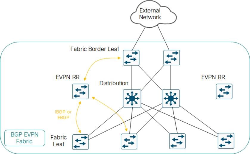
For organizations looking for an open standards-based overlay solution for their campus designs, and not needing the full intent-based networking security solution along with integrated wireless, BGP EVPN VXLAN can be a viable alternative to traditional campus virtualization options.
Design Fundamentals: LAN Security Best Practices
With any good network design, security must also be a focus. These tools below can help prevent attacks and make the network more secure and reliable.
Note: These are a few fundamental tools to help with basic network security, check out the Enterprise Security Design Guide for a more in depth look at campus security.
DHCP Snooping
Rogue DHCP servers can be detrimental to the security and usability of the network if not protected against properly. Rogue DHCP servers attack the network by assigning unrouteable IP addresses to clients causing them to lose connectivity. Also, Rogue DHCP servers can be used to issue malicious DNS servers. Users then looking to go to real websites will be sent to fake copies of these sites to steal credentials or information.
DHCP Snooping is a tool used to combat rogue DHCP servers. It works by assigning one or more ports as trusted, meaning these ports lead to legitimate DHCP servers. The switch will then build a database of the untrusted hosts with leased IP addresses, MAC Address, switchport, and VLAN. Traffic being sent from these untrusted hosts will be filtered of any DHCP server messages, blocking any attempt of a malicious DHCP server.
Dynamic ARP Inspection
ARP cache poisoning is a malicious tool used to stage man-in-the middle attacks. It works by sending a forged ARP packet with the IP address of another device and the MAC address of itself to poison hosts ARP cache. This means traffic destined for the legitimate device will instead be sent to the attacker. The attacker can then forward the traffic to its intended destination making it look as if the traffic was never interrupted.
Dynamic ARP Inspection (DAI) is a tool that can be used to mitigate this threat. DAI uses the DHCP snooping database for IP to MAC address bindings. DAI then intercepts all ARP packets and drops any packet where the IP to MAC address binding is not valid.
BPDU Guard
In L2 networks, loops can be your worst nightmare. To combat this, we use STP (Spanning Tree Protocol), but this can also be used to hurt the network if we don’t protect it.
In spanning tree, a root bridge is elected. This decides which ports will be put in a forwarding or blocking state. If a device is added with a lower priority than the current root bridge, it will take over causing a topology change and possibly blocking traffic from a wanted path.
BPDU guard is a protocol designed to solve this problem. When enabled, if a switch sees BDPU traffic coming from a port, it will automatically set it to the “errdisabled” state so that no traffic can pass.
802.1X
Authentication is very important for the security of the network. A potential attacker can sneak into a building and plug into an enabled network port and gain access to the network.
802.1X is an IEEE standard used for restricting unauthorized access to the network by making users authenticate before they are allowed onto the network. 802.1X uses three different parts for authentication.
· Supplicant – This is software which runs on the user device that collects credentials and forwards them to be authenticated.
· Authenticator – This is the network access device, usually a switch, the supplicant sends the user credentials to. The credentials are then forwarded to the authentication server.
· Authentication server – This is a RADIUS server that validates the credentials based off information in its database.
Cisco Umbrella
With remote workers and sites being more prevalent in today’s networks, it can be difficult to secure the network from malware and phishing attacks.
Cisco Umbrella provides a first line of security for wherever users access the internet by using DNS as a security tool. Since DNS is a core part of the internet, it is used to block requests to malicious domains and IP addresses before a connection is established. It learns of these current and future threats through a growing database built on machine learning and Internet activity patterns. This means Cisco Umbrella can identify and block threats before they even launch.
Cisco Umbrella also provides network administrators visibility of Internet activity across all endpoint devices on or off the corporate network. This allows users to easily view any malicious domains or IP addresses attempted to be accessed by users.
Design Fundamentals: LAN High Availability
To mitigate the concerns about unavailability of network resources, campus LAN designs include high availability / resiliency options, such as redundant links, switches, and switch components. Designing for high availability in the LAN must also consider the entire lifecycle of the deployment, including the need for updates and upgrades on the network. This section discusses high availability features specific to the LAN side of the network.
Stateful Switchover (SSO)
Stateful switchover (SSO) synchronizes active process information, as well as configuration information, between active and standby supervisors of a modular chassis / StackWise Virtual pair, or between the active and standby switches in a switch stack. SSO allows the standby supervisor / switch to immediately take over in sub-second time if the active supervisor / switch fails.
Non-stop Forwarding (NSF)
Non-stop forwarding (NSF) helps to suppress routing flaps in SSO enabled devices. NSF allows for graceful restart of L3 routing protocols, in the event of the failure of the active supervisor of a modular chassis / StackWise Virtual pair, or the failure of the active switch of a switch stack. When the supervisor or switch switches over from the active to the hot-standby, it will continue switching IP data traffic flows in hardware. However, the device in the active role requires time to re-establish control plane peering with IP routing neighbors. NSF allows for the forwarding of data packets to continue along known routes while the routing protocol information is being restored following a switchover.
Supervisor Redundancy
Cisco Catalyst C9404R, C9407R, C9410R, and C9606R chassis models support 1+1 supervisor redundancy (Sup-1, Sup1XL, or Sup-1XL-Y on Catalyst 9400 Series, and Sup-1 on Catalyst 9600 Series). The primary supervisor is active and is responsible for normal system operation. The secondary supervisor serves as a standby, monitoring the operation of the primary. Information is synchronized between supervisors to allow the standby supervisor engine to immediately take over in sub-second time if the primary engine fails. Non-stop forwarding / stateful switchover (NSF / SSO) offers continuous packet forwarding during supervisor engine switchover.
Note: When implementing 1+1 supervisor engines on Catalyst 9400 Series switches, the active uplink ports are automatically spread across the two supervisors for link-level resiliency. The Catalyst 9600 Series supervisor engine does not support uplinks on the module itself. For link-level resiliency on the Catalyst 9600 Series, spread uplinks ports across the switch linecards.
StackWise Virtual Technology
StackWise Virtual technology combines two Catalyst 9000 Series switches into a single logical network entity from the network control plane and management perspectives. Because the two switches operate as one, StackWise Virtual enables the creation of a loop-free topology. Spanning-tree treats the StackWise Virtual pair as one bridge node, instead of two. StackWise Virtual technology uses SSO / NSF to provide seamless traffic failover when one of the switches fails. To neighboring devices a StackWise Virtual domain appears as a single logical switch or router. Within a StackWise Virtual domain, one device is designated as the active switch and the other is designated as the standby switch. All control plane functions are centrally managed by the active switch. From the data-plane and traffic-forwarding perspectives, both switches actively forward traffic.

In order to bond the two switches together into a single logical node, special signaling and control information must be exchanged between the two switches. To facilitate this information exchange, a dedicated link – the StackWise Virtual link (SVL) – is used to transfer both data and control traffic between the peer switches. The SVL is formed as an EtherChannel interface of up to eight physical port members. It is recommended to have at least two physical port members for StackWise Virtual link resiliency.
Switch Stacks and Cisco StackWise Technology
Cisco StackWise technology allows up to a maximum of eight switches to be stacked together physically in a ring topology to form a single, unified, virtual stack system. The stacking architecture expands form factor, switching capacity, port density, and redundancy, as well as providing a distributed data plane with a single control and management plane.
StackWise creates a unified control and management plane by electing one switch in the stack as the active switch and another switch as the hot-standby. Remaining switches become stack members. To logically appear as a single virtual switch, the IOS daemon (IOSd) process on the active switch of the stack centrally manages all management plane and network control plane operations with Layer 2 and Layer 3 protocols. This information is synchronized with the standby switch of the stack to provide NSF / SSO failover in case the active switch fails. To optimize data plane performance by using hardware resources from each Catalyst 9000 Series stack member switch, network services such as QoS, security ACLs, and others are distributed and programmed to be locally enforced on network ports. The hardware Forwarding Information Base (FIB) is also programmed in ASICs across all stack-member switches in the stack ring.
To optimally forward the traffic within the stack ring, the packet-stripping function is performed on the destination switch instead of on the source switch. This mechanism, known as the spatial-reuse forwarding mechanism, boosts data plane switching performance in the stack-ring switching architecture.
The following sub-sections discuss the StackWise implementation on Catalyst 9200 and 9300 Series switches.
Catalyst 9200 Series StackWise-160/80
Catalyst 9200 Series switches enable stacking of up to 8 switches and 416 ports using a stack-ring fabric known as either StackWise-160 or StackWise-80. StackWise-160 is supported on Catalyst 9200 switch models with the support of up to 160 Gbps stack bandwidth. StackWise-80 is supported on Catalyst 9200L switch models with the support of up to 80 Gbps stack bandwidth.
Catalyst 9300 Series StackWise-480/360
Catalyst 9300 Series switches enable stacking of up to 8 switches and 448 ports using a stack-ring fabric known as either StackWise-480 or StackWise-360. StackWise-480 is supported on Catalyst 9300 switch models with the support of up to 480 Gbps stack bandwidth. StackWise-360 is supported on Catalyst 9300L switch models with the support of up to 360 Gbps stack bandwidth.
EtherChannel
EtherChannel allows multiple physical Ethernet links to combine into one logical channel, allowing for load sharing of traffic among the links in the channel as well as redundancy in the event that one or more links in the channel fail. Up to eight Ethernet ports can be combined into a single logical channel. Multichassis EtherChannel (MEC) and cross-stack EtherChannel extend traditional EtherChannel by allowing Ethernet ports to be aggregated towards different physical chassis that form a single virtual switch (StackWise Virtual pair or switch stack).
Software Maintenance Upgrades (SMUs)
An SMU is a software package that can be installed on Catalyst 9000 Series switches to provide a patch fix for bugs or security resolution to an already released image. The SMU type describes the effect the installed SMU has on the corresponding system. SMUs might not have an impact on traffic, or might result in device restart, reload, or switchover. Hot patching enables SMU to take effect after activation without the system having to be reloaded. After the SMU is committed, the changes are persistent across reloads. In certain cases, SMUs may require a cold (complete) reload of the operating system. This action affects the traffic flow for the duration of the reload. If a cold reload is required, users will be prompted to confirm the action.
Note: SMUs support patching using install mode only. SMUs are only supported on long-lived extended maintenance releases from IOS XE 16.6.1 on.
In-Service Software Upgrades (ISSUs)
In-Service Software Upgrade (ISSU) is a process that upgrades an image to another image on a device while the network continues to forward packets. ISSU helps network administrators avoid a network outage when performing a software upgrade. The images are upgraded in install mode wherein each package is upgraded individually. ISSU is supported in Catalyst 9000 Series standalone and modular platforms (Catalyst 9400, 9500, and 9600 Series).
Note: ISSU is not supported for an upgrade from Cisco IOS XE Fuji 16.9.1 to Cisco IOS XE Fuji 16.9.2. ISSU from Cisco IOS XE Fuji 16.9.x to Cisco IOS XE Gibraltar 16.10.x or Cisco IOS XE Gibraltar 16.11.x is not supported. On Cisco Catalyst 9500 Series Switches - High Performance, ISSU with Cisco StackWise Virtual is supported starting from Cisco IOS XE Gibraltar 16.12.1. Therefore, ISSU upgrades can be performed only starting from this release to a later release.
Graceful Insertion and Removal (GIR)
GIR leverages redundant paths and existing routing protocols to gracefully isolate a device without impacting active flows. Conversely, GIR also gracefully reinserts the device back into service when the work is complete. GIR allows the network administrator to easily manipulate the routing and first-hop gateway metrics of a network device that is about to undergo maintenance to make it a very unattractive path. It does this by inflating metrics or sending messages to indicate to peers that this device is no longer the best path for traffic. Once the traffic moves away from the device, maintenance actions can be undertaken. Once the maintenance is complete, returning these metrics to their former values then smoothly restores normal traffic flow.
Fast Software Upgrade (FSU) and Extended Fast Software Upgrade
During a software upgrade on the switch, user traffic is disrupted until the new software completely boots up. The traffic downtime is a concern for customers running critical applications. The Fast Software Upgrade (FSU) feature significantly reduces the traffic downtime during a software upgrade. The fast software upgrade feature is supported on both stacking and standalone systems from IOS XE 16.8.1a and higher.
Note: Fast software upgrade is supported only on access switches with a single logical uplink connection. Fast software upgrade is not supported if the Micro Controller Unit (MCU) Field Programmable Gate Array (FPGA) upgrade is required. Fast software upgrade is not supported if the switch is configured as StackWise Virtual System.
Extended Fast Software Upgrade reduces the traffic downtime during software reload or upgrade operations. Compared to Fast Software Upgrade, the traffic downtime is reduced to less than 30 seconds, depending on the switch configuration. Extended Fast Software Upgrade uses graceful restart capability (a feature of Cisco NSF) to ensure that device configurations, such as certain routing protocols, remain unaffected during a software upgrade or reload.
The following table summarizes high availability support with the various Catalyst 9000 Series switches.
Table 1. High availability feature support
| Platform |
Switch Stacking |
Supervisor Redundancy |
NSF / SSO |
EtherChannel |
ISSU |
SMUs |
GIR |
Power Redundancy |
| Cisco Catalyst 9200 Series |
StackWise-160/80 with Active / Standby |
— |
Yes |
Cross-Stack EtherChannel |
No |
Yes |
No |
Up to 2 hot-swappable power supplies per switch. PoE models operate in Combined mode. Non-PoE models operate in 1:1 redundancy mode. |
| Cisco Catalyst 9300 Series |
StackWise-480/360 with Active / Standby |
— |
Yes |
Cross-Stack EtherChannel |
No. Supports Fast Software Upgrade (FSU) and Extended FSU. |
Yes |
Yes |
StackPower (up to 4 switches per stack) operating in shared or redundant mode. Cisco XPS 2200 for stacks of up to 8 switches |
| Cisco Catalyst 9400 Series |
— |
Single chassis 1:1 or cross chassis StackWise Virtual |
Yes |
Multichassis EtherChannel with StackWise Virtual |
Yes |
Yes |
Yes |
Hot-swappable power supplies in N+N or N+1 power redundancy modes |
| Cisco Catalyst 9500 Series |
— |
Cross chassis StackWise Virtual |
Yes |
Multichassis EtherChannel with StackWise Virtual |
Yes |
Yes |
Yes |
Dual 1+1 redundant power supplies. |
| Cisco Catalyst 9600 Series |
— |
Single chassis 1:1 or cross chassis StackWise Virtual |
Yes |
Multichassis EtherChannel with StackWise Virtual |
Yes |
Yes |
Yes |
Four power supplies which can operate in Combined or N+1 redundancy modes. |
Design Fundamentals: Campus Wireless LAN
The campus WLAN provides ubiquitous data and voice connectivity for employees, wireless Internet access for guests, and connectivity for IoT devices. With the emergence of high-density networks and the IoT, organizations are more dependent on wireless networks than ever before. Increasing numbers of devices connect to the network every year, ranging from high-performance client devices to low-bandwidth IoT devices.
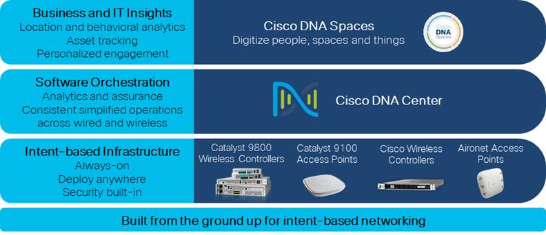
Cisco wireless solutions are resilient, have the integrated security organizations need, and employ adaptive and insightful intelligence providing useful insight into the network. With intent-based networking built on Cisco Digital Network Architecture (Cisco DNA), our wireless solutions go beyond the latest Wi-Fi 6 (802.11ax) standard and are ready for the growing user expectations, IoT devices and next gen cloud-driven applications. With the ability to handle the increased mobile traffic as well as support IoT at scale, Cisco’s first Wi-Fi 6 APs with superior RF innovations expand wireless access with intelligence and provide a secure, reliable high quality wireless experience for all networks.
Regardless of their location within the organization—on large campuses or at remote sites—wireless users have the same experience when connecting to voice, video, and data services.
Infrastructure
The next-generation wireless stack is built around these main hardware and software components:
● Cisco Catalyst 9800 Series WLAN controllers (including appliances, virtual, and embedded)
● Cisco Catalyst 9100 Wi-Fi 6 APs
● Cisco DNA Center (assurance and automation)
● Cisco Prime Infrastructure (additional automation for more complex deployments)
● Cisco DNA Spaces
Cisco Catalyst 9800 Series wireless controllers
Cisco Catalyst 9800 Series wireless controllers combine RF excellence with Cisco IOS-XE benefits. These highly reliable and highly secure controllers are ready to deploy anywhere—including the cloud. An organization can also choose the Cisco Embedded Wireless Controller on Cisco Catalyst 9100 Series APs, for Cisco Catalyst controller features without a dedicated appliance.
Cisco Catalyst 9800 Series wireless controllers are built on the three pillars of network excellence—always on, secure, and intelligent—which strengthen the network by providing the best wireless experience without compromise, while saving time and money.
● Always on—Seamless software updates enable faster resolution of critical issues, introduction of new APs with zero downtime, and flexible software upgrades. High availability stateful switchover (HA SSO), described later, with 1:1 active standby and N+1 redundancy keeps the network, services, and clients always on, even in unplanned events.
● Secure—Secure air, devices, and users with Cisco Catalyst 9800 Series wireless controllers. Wireless infrastructure becomes the strongest first line of defense with ETA and Cisco SD-Access. The controller comes with built-in security: secure boot, runtime defenses, image signing, integrity verification, and hardware authenticity.
● Intelligent—Cisco Catalyst 9800 Series wireless controllers are built on the modular Cisco IOS XE operating system, which offers a rich set of open standards-based programmable APIs and model-driven telemetry that provide an easy way to automate day-0 to day-N network operations, and deep insights into the health of your network and clients. When paired with Cisco DNA, your network works for you. Whether it’s providing you with enhanced analytics or being deployed in the infrastructure (including the Cloud) of your choice, the Cisco Catalyst 9800 Series gives you the choices you need for better efficiency.
Cisco WLAN controllers are responsible for system-wide WLAN functions, such as security policies, intrusion prevention, RF management, QoS, and mobility. They work in conjunction with Cisco APs in order to support business-critical wireless applications. From voice and data services to location tracking, Cisco WLAN controllers provide the control, scalability, security, and reliability that network managers need to build secure, scalable wireless networks.
The following table summarizes the Cisco WLAN controllers referenced within this guide.
Table 2. WLAN controller platforms
| Deployment Mode |
Preferred Topology |
Maximum APs |
Maximum Clients |
Controller Throughput |
|
| Cisco Catalyst 9800-80 |
Centralized, |
Large Campus |
6,000 |
64,000 |
Up to 80 Gbps |
| Cisco Catalyst 9800-40 |
Centralized, |
Medium Campus |
2,000 |
32,000 |
Up to 40 Gbps |
| Cisco Catalyst 9800-L |
Centralized, |
Small Campus / Remote Site |
250 |
5,000 |
Up to 5 Gbps |
| Cisco Catalyst 9800-L with Performance License |
Centralized, |
Small Campus / Remote Site |
500 |
10,000 |
Up to 9 Gbps |
| Cisco Catalyst 9800 embedded on Cisco Catalyst 9000 Series Switches |
SD-Access |
SD-Access Small Distributed Site |
200 |
4,000 |
— (local switching) |
| Cisco Catalyst 9800 Embedded on Catalyst 9100 Series Access Points (EWC) |
Local Switching |
Small Remote Site |
100 |
2,000 |
— (local switching) |
| Cisco Catalyst 9800-CL for |
FlexConnect with Local Switching |
Virtual Controller for Small Remote Sites |
1,000, |
10,000, |
— (local switching) |
| Cisco Catalyst 9800-CL for Private Cloud |
Centralized, |
Virtual controller for Small, Medium, or Large Sites |
1,000, |
10,000, |
Up to 2.1 Gbps with Central Switching (IOS XE 17.1 and higher) |
Additional scale numbers, including maximum Site Tags, Flex APs per site, Policy Tags, RF tags, RF Profiles, Policy Profiles, and Flex Profiles can be found in the datasheets of individual wireless controller platforms.
Because software license flexibility allows you to add additional APs when requirements of an organization change, you can choose the controller that will support your needs long term, but you purchase incremental access point licenses only when you need them.
Cisco Catalyst 9800 Series configuration model
The Cisco Catalyst 9800 Series wireless controller configuration data model is based on design principles of reusability, simplified provisioning, enhanced flexibility and modularization to help manage networks as they scale up and simplify the management of dynamically changing business and IT requirements. The configuration model maps APs to three types of tags - policy tags, site tags, and RF tags.
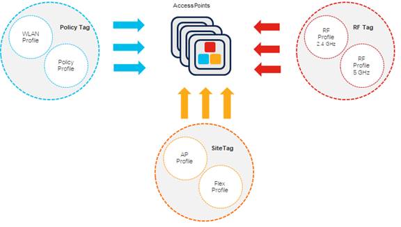
Wireless clients and APs derive their configurations from the profiles contained within the tags. The properties of a tag are defined by the policies defined within profiles associated with the tag. Profiles represent a set of attributes that are applied to the wireless clients associated to the APs or to the APs themselves. Profiles are reusable entities that can be used across tags.
Policy tags
Policy tags define the broadcast domain (list of WLANs to be broadcast) within the policies of the respective SSIDs. For ease of deployment, tags can be assigned based on location and filter, as opposed to statically assigning tags. Policy tags are associated with a WLAN profile and a policy profile—each with their respective attributes shown in the figure below.
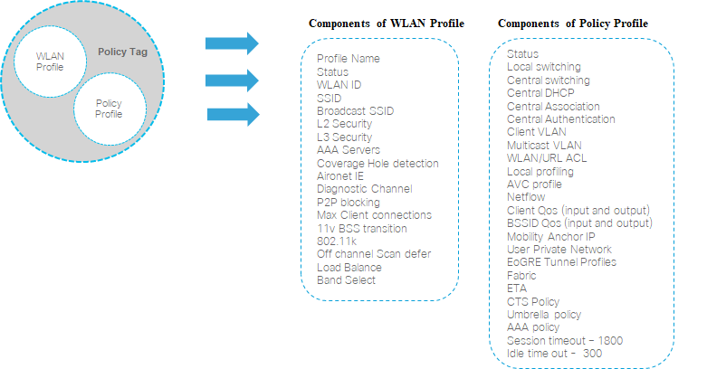
Profiles may include additional components, not listed in the figure above.
Site tags
Site tags define the properties of the central and remote sites. They also define the roaming domain for Cisco FlexConnect APs in a Cisco FlexConnect deployment. Site tags are associated with an AP Join Profile and a Flex Profile - each with their respective attributes shown in the figure below.
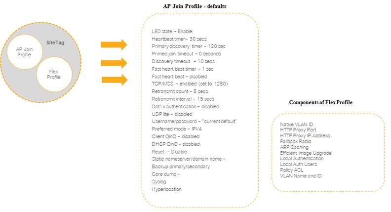
Profiles may include additional components, not listed in the figure above.
RF tags
RF tags define the properties of the group of APs. RF tags are associated with a 2.4 GHz RF Profile and a 5 GHz RF Profile - with their respective attributes shown in the figure below.
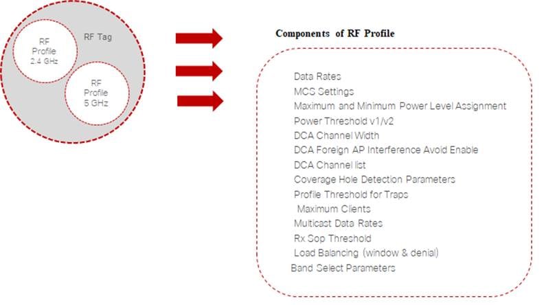
Profiles may include additional components, not listed in the figure above.
Cisco Catalyst 9800 Series wireless controller configuration can be managed using Cisco DNA Center, NETCONF/YANG, Cisco Prime Infrastructure, the web-based graphical user interface (GUI), or the command line interface (CLI).
Cisco Catalyst 9100 Series APs
Cisco Catalyst 9100 Series APs can handle the challenges of the next-generation network. Going beyond the Wi-Fi 6 (802.11ax) standard, Cisco Catalyst 9100 Series APs are resilient and intelligent and provide integrated security for mobile clients and IoT devices. Key benefits of the Cisco Catalyst 9100 Series APs include the following:
● Wi-Fi 6 and beyond—Wi-Fi 6 reduces latency and increases capacity for demanding applications on more devices. Cisco improves on it with programmable RF ASICs. We advance more wireless efficiency with Intelligent Capture, which provides Cisco DNA Center with deep analysis.
● Addresses IoT expansion—The Cisco Catalyst 9100 Series offers multilingual support and application hosting of IoT protocols. In addition, IoT devices (as well as user devices) can see up to three times less energy consumption and more stringent security.
● Investment protection with multigigabit—The Cisco Catalyst 9100 Series supports NBASE-T and IEEE 802.3bz Ethernet compatibility to seamlessly offload network traffic without bottlenecks. With Cisco Catalyst switches and Cisco Multigigabit Technology, you can use your Category 5e or 6 cables to achieve speeds up to 10 Gbps.
● Available with embedded control—You can choose an option that is easy to deploy and manage and doesn't require a physical appliance. Cisco Catalyst 9800 Embedded Wireless Controller (EWC) can be built right into the access point.
The following table summarizes the APs discussed within this guide.
Table 3. Cisco Aironet APs
* Radio available for future use
Support for two key technologies differentiates the APs selected for deployment in the campus WLAN:
● 802.11ax (Wi-Fi 6)—The IEEE 802.11ax (Wi-Fi 6) specification provides for significant enhancements to wireless networking performance including the following:
◦ Higher capacity: Attach more devices than under previous standards through features such as orthogonal frequency-division multiple access (OFDMA) and multiuser multiple-input multiple-output (MU-MIMO). Wi-Fi 6 communicates in parallel with devices, whereas existing standards communicated only "one at a time".
◦ Improved power efficiency: Using target wake time (TWT), client devices that support the Wi-Fi 6 standard may consume less power. This means that batteries in products such as smartphones, laptops, tablets, and IoT devices can last longer, which makes it the ideal standard.
◦ Reduced data latency by optimizing packet scheduling, which is ideal for voice, video and gaming applications.
◦ Greater IoT coverage by bringing the benefits of Wi-Fi 6 to the 2.4- GHz band.
◦ Increased speed: Gain an increase in average throughput in congested wireless environments.
◦ Improved security: WPA3 is certified with Wi-Fi 6 and provides a greater value proposition than WPA2 for enterprise Wi-Fi networks. It offers enhanced security for open Wi-Fi networks with encryption of unauthenticated traffic, robust password protection against brute-force dictionary attacks, and superior data reliability for sensitive information with 192-bit encryption.
● Cisco RF ASIC—The custom Cisco RF ASIC, available within the Cisco Catalyst 9120AX and 9130AX Series APs, provides enhanced off-channel monitoring, improving serving radio performance by as much as 25 percent, as well as Flexible Radio Assignment (FRA), CleanAir, wireless intrusion prevention system (WIPS) and DFS detection. This silicon-level intelligence creates a self-healing, self-optimizing wireless network that mitigates the impact of wireless interference.
Cisco DNA Spaces
Cisco DNA Spaces provides organizations with rich location-based wireless services, including location analytics, business, insights, customer engagement toolkits, asset management, enterprise integrations, and location data APIs. This cloud-based platform, which is compatible across Cisco Aironet, Cisco Catalyst and Cisco Meraki wireless APs, lets your enterprise see activity at its properties, act on these insights and extend platform capabilities via integrations and partner applications.
With Cisco DNA Spaces you gain the following benefits:
● Simplification: A single, unified platform for accessing location products and apps and for normalizing data to create meaningful insights
● Cloud first, scalable: A cloud-first software-as-a-service (SaaS) approach that enables presence and location connection to the cloud across the entire installed base
● Standardization: Compatibility and interoperability across all Cisco wireless—Cisco Aironet, Cisco Catalyst, and Cisco Meraki
● Support: 24x7 monitoring and service-level agreements (SLAs) for end-to-end reliability
● Low touch: No need to upgrade your underlying network infrastructure to activate service
Cisco DNA Spaces takes the wireless network beyond connectivity to drive digitization in three easy steps: See, Act, and Extend.
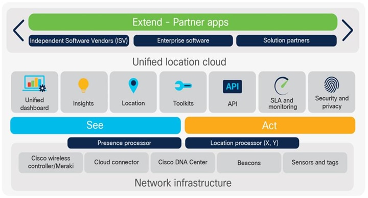
Now you can see what's happening at your properties, act on this knowledge through digitization toolkits, and extend platform capabilities by leveraging a partner app ecosystem.
Cisco DNA Spaces provides support for all wireless deployment modes.
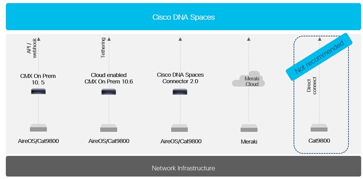
An on premises deployment of Cisco DNA Spaces is required for the following:
● Hyperlocation—To use the Cisco Aironet 4800 Series or 3700 Series APs with a hyperlocation antenna, or to use fast path on all APs on an on-premises server, it is required to receive fast path UDP data on port 2003 from the access point and use it for location calculations.
● Integration with Cisco DNA Center or Prime Infrastructure—To provide location data to Cisco DNA Center or Prime Infrastructure, an on-premise server is currently required.
Wireless design models
This guide describes the following design models and their recommended use:
● Centralized (local-mode) design model
● Cisco FlexConnect design model
● Cisco SD-Access Wireless design model
● Cisco Catalyst 9800 Embedded on Catalyst 9100 Series APs (EWC) design model
Centralized (local-mode) design model
A centralized design model, also known as a local-mode design model, is recommended primarily for large site deployments. The benefits of a centralized design include IP address management, simplified configuration and troubleshooting, and roaming at scale. In a centralized design model, the WLAN controller and APs are both located within the same site.
You can connect the WLAN controller to a data center services block, a separate services block off of the campus core, or a LAN distribution layer. Wireless traffic between WLAN clients and the LAN is tunneled by using the control and provisioning of wireless APs (CAPWAP) protocol between the controller and the AP. This has the advantage of decoupling the subnet on which the wireless clients terminate from the AP; requiring the availability of the wireless client VLAN only at the controller, thus simplifying the deployment.
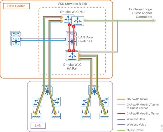
A centralized architecture uses the controller as a single point for managing Layer 2 security and wireless network policies. It also enables services to be applied to wired and wireless traffic in a consistent and coordinated fashion.
The local-mode design model meets the following organization demands:
● Seamless mobility—Enables fast roaming across the campus, so that users remain connected to their session even while walking between various floors or adjacent buildings with changing subnets
● Ability to support rich media—Enhances robustness of voice with call admission control and multicast with Cisco VideoStream technology
● Centralized policy—Enables intelligent inspection through the use of firewalls, as well as application inspection, network access control, policy enforcement, and accurate traffic classification
If any of the following are true at a site, you should consider deploying a controller locally at the site:
● The site has a data center.
● The site has a LAN distribution layer.
● The site has more than 100 APs.
● The site has a WAN latency greater than 100ms round-trip to a proposed shared controller.
The recommended platforms for large centralized (local-mode) designs are the Cisco Catalyst 9800-80 and 9800-40 WLAN controllers, because of their scalability and feature support. For smaller sites, you can deploy the Cisco 9800-L WLAN controller as a local controller within the site. The Cisco Catalyst 9800-CL virtual form factor deployed within a private cloud is another alternative and includes the same feature set as the Cisco Catalyst 9800 Series appliances.
Cisco FlexConnect design model
Cisco FlexConnect is a wireless solution primarily for deployments that consist of multiple small remote sites (branches) connected into a central site. Cisco FlexConnect provides a highly cost-effective solution, enabling organizations to configure and control remote-site APs from the headquarters through the WAN, without deploying a controller in each remote site.
Cisco APs operating in Cisco FlexConnect mode can switch client data traffic out their local wired interface and can use 802.1Q trunks in order to segment multiple WLANs. The trunk's native VLAN is used for all CAPWAP communication between the AP and the controller. This mode of operation is referred to as Cisco FlexConnect local switching and is the mode of operation described in this guide.
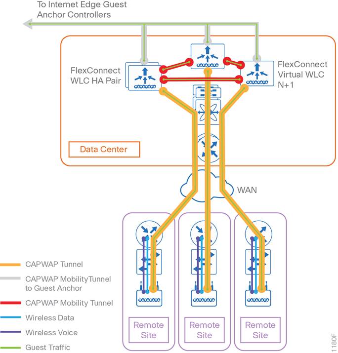
Cisco FlexConnect can also tunnel traffic back to the centralized controller, which can be used for wireless guest access. You can use a shared controller pair or a dedicated controller pair in order to deploy Cisco FlexConnect.
In a shared controller model, both local-mode and Cisco FlexConnect configured APs share a common controller. A shared controller architecture requires that the WLAN controller support both Cisco FlexConnect local switching and local mode. In this guide, the WLAN controllers that support both are the Cisco Catalyst 9800-80, 9800-40, 9800-L Series appliances and the Cisco Catalyst 9800-CL for private cloud wireless controllers.
You may be able to use a shared deployment if you meet all the following requirements:
● You have an existing local-mode controller pair at the same site as your WAN aggregation.
● The controller pair has enough additional capacity to support the Cisco FlexConnect APs.
● The number of site tags with Cisco FlexConnect profiles required matches the capabilities of the controller pair.
If you don't meet the requirements for a shared controller, you can deploy dedicated Cisco Catalyst 9800-80, 9800-40, or 9800-L Series wireless controllers. The Cisco Catalyst 9800-CL virtual form factor, deployed in either a private cloud or public cloud is an alternative to an appliance, since wireless traffic is typically locally terminated in a Cisco FlexConnect deployment. The Cisco Catalyst 9800-CL deployed within a public cloud only supports Cisco FlexConnect with local termination. The Cisco Catalyst 9800-CL deployed within a private cloud supports local termination as well as centralized termination of wireless traffic, although at lower scale (up to 1.5 Gbps) than a dedicated controller appliance.
For highest resiliency, deploy a pair of controllers in HA SSO configuration. Alternatively, you can deploy N+1 high availability in order to provide cross-site resiliency if desired. With N+1 HA, APs are configured with a primary, secondary, and even a tertiary WLC, as desired. If connectivity to the primary WLC fails (the CAPWAP tunnel goes down), the AP establishes connectivity to the secondary WLC – potentially deployed at a different regional geographic location.
If all of the following are true at a site, you should consider deploying Cisco FlexConnect at the site:
● The site LAN is a single access-layer switch or switch stack.
● The site has fewer than 50 APs.
● The site is one of many small remote sites connected to a central location
● The site has a WAN latency less than 100ms round-trip to the shared controller.
Cisco SD-Access Wireless design model
Cisco SD-Access Wireless is the fabric-enabled wireless solution that, unlike any alternative solution, fully integrates with a wired Cisco SD-Access model. The primary benefit of Cisco SD-Access Wireless is that organizations can have a common policy and unified experience across both wired and wireless. In this model, the fabric WLCs communicate wireless client information to the fabric control plane, and the fabric APs encapsulate traffic into the VXLAN data path.
Note: SD-Access Wireless control plane traffic is passed to the WLC, while data plane traffic is passed directly into the fabric. The distributed data plane allows the solution to scale more easily, avoids hair-pinning of wireless traffic through the wireless controller, and retains the ability to easily stretch the Layer-2 domain.
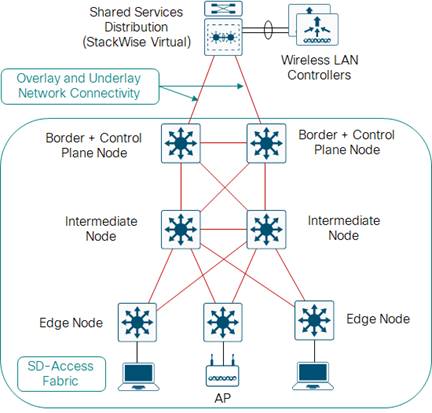
Requirements for deploying Cisco SD-Access Wireless:
● Cisco SD-Access wired fabric deployment
● APs with fabric mode support directly connected to Cisco SD-Access fabric edge nodes
● WLC with fabric mode control plane support
● 20ms or less latency between the fabric APs and the fabric WLC
● Cisco SD-Access Wireless design model
Cisco Catalyst 9800 Embedded on Catalyst 9100 Series APs (EWC) wireless design model
The Cisco EWC is a Wi-Fi solution using a Cisco Catalyst 9800 Series Wireless Controller embedded into the Cisco Catalyst 9100 Series APs. The Cisco EWC is an alternative to Cisco FlexConnect deployments for small wireless deployments, since a separate on-premise controller does not need to be deployed.
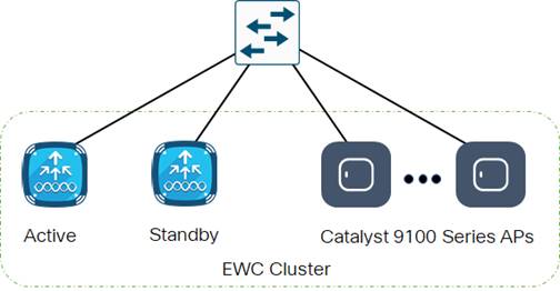
The Cisco EWC platform provides the following benefits:
● High availability with active and standby controllers running simultaneously on two Cisco Catalyst 9100 Series APs (configuration synchronization, not HA SSO)
● Software maintenance updates (SMUs) providing hot patching of the controller, AP device packs, and AP service packs supported, like standalone controllers
● Cisco DNA Center support for Plug and Play, Automation, and Assurance, including Intelligent Capture (similar to other deployment models)
● Advanced RF features such as Flexible Radio Assignment (FRA) and Cisco CleanAir technology (similar to other deployment models)
● Automatic configuration of wireless best practices from more than 10 years of experience with large and medium-scale implementations
If the following are true, you should consider deploying the EWC at the site:
● Single site or multisite enterprise locations with up to 100 APs and 2,000 clients per site for Cisco Catalyst 9120AX or 9130AX Series running EWC; or up to 50 APs and 1,000 clients per site for Cisco Catalyst 9115AX and 9117AX Series running EWC.
● Guest Anchor is not required (currently not supported on the EWC).
● Layer 2 roaming only, without mobility groups.
Note: Cisco 802.11ac Wave 2 APs can join a Cisco EWC network and service clients, but Cisco 802.11ac Wave 2 APs cannot run the EWC function.
Design Options: Campus Wireless LAN
AP site tag considerations
Cisco Catalyst 9800 Series wireless LAN controllers have a multi-process architecture. Multiple wireless network controller processes (WNCd) run within a single Cisco Catalyst 9800 platform. The number of WNCd instances varies from platform to platform.
APs (and wireless clients) are load balanced across the WNCd instances for better scale and performance. In recent software releases, APs are load balanced across the WNCd instances based upon the site tag applied to the AP. If the default site tag is used, APs are load balanced across the WNCd instances in a round robin fashion.
Roaming and fast roaming work across site tags. However, 802.11k assisted roaming, 802.11v BSS transition, coverage hole detection (CHD), and other proximity based features are managed within individual WNCd instances. Therefore, a best practice design recommendation is to configure custom site tags, and not use the default site tag. For best performance, use a custom site tag to group APs within a roaming domain. Also, a best practice is to limit the maximum number of APs per site tag to 400 APs.
The following are recommendations based on specific deployments:
● If the deployment has a building with more than 400 APs, consider splitting the building into two parts from site tag perspective. Each part should have its own custom site tag with less than 400 APs.
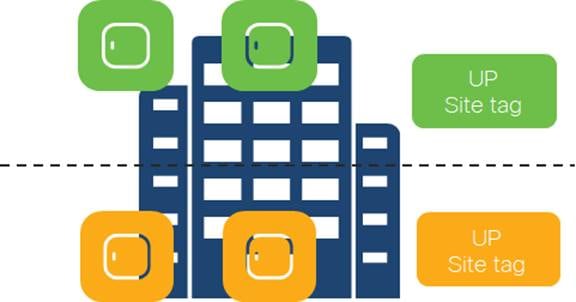
● If the deployment has a roaming domain that spans across multiple buildings, with more than 400 APs, consider configuring a Site Tag per building.
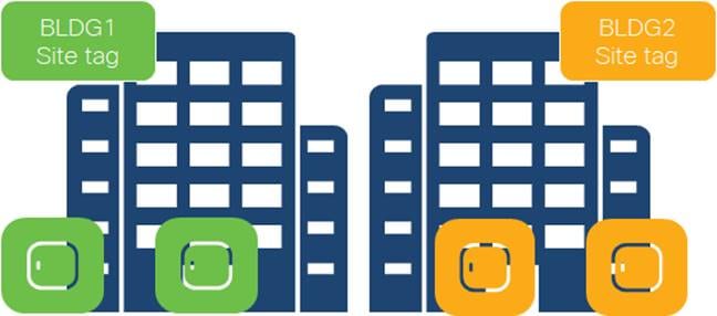
● If the deployment has multiple buildings, with less than 400 APs, consider configuring a single custom site tag. Don't use the default site tag.
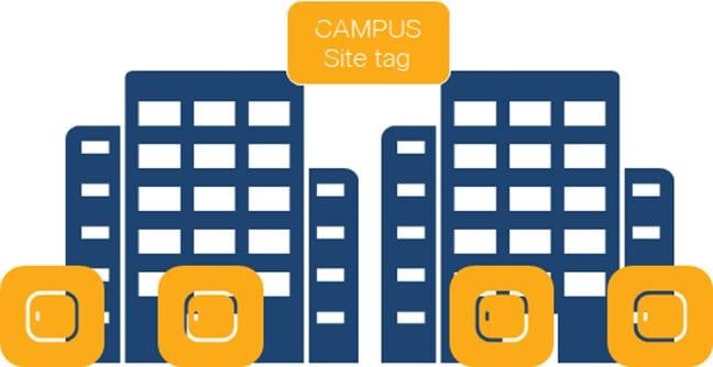
● When deploying Cisco FlexConnect, set the site tag to be a non-Local Site within the Cisco Catalyst 9800 configuration. When the Local Site option is disabled, the site tag is equivalent to a Cisco FlexConnect Group in classic Cisco AireOS wireless controllers.
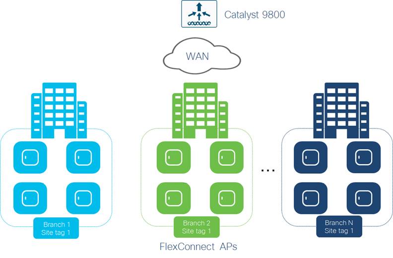
There is a limit of 100 APs per Cisco FlexConnect site tag for seamless roaming. Roaming across site tags for Cisco FlexConnect APs results in a client full reauthentication.
High availability
As more devices with critical functions move to the wireless medium, high availability of the wireless infrastructure is becoming increasingly important. Real-time audio, video, and text communication relies on the corporate wireless network, and the expectation of zero downtime is becoming the norm. The negative impacts of wireless network outages are just as impactful as outages of the wired network. Implementing high availability within the wireless infrastructure involves multiple components and functionality deployed throughout the overall network infrastructure, which itself must be designed for high availability. This section discusses high availability specific to the implementation of wireless controller platforms. Platform-level redundancy refers to the ability to maintain wireless service when connectivity to one or more physical WLAN controller platforms within a site is lost.
Designing for high availability must also consider the entire lifecycle of the deployment, including the need for updates and upgrades on the network. This section also discusses the use of software maintenance updates (SMUs) for wireless controller fixes and updates, AP service packs (APSPs) for AP fixes and updates, and AP device packs for support for new AP models
The methods of high availability discussed within this design guide, available with releases of Cisco IOS-XE 17.1 and higher, are as follows:
● High availability SSO
● N+1 high availability
● WLAN controller link aggregation
● Wireless controller patches using software maintenance updates (SMUs)
● AP patches using AP service packs (APSPs)
● Support for new AP models using AP device packs (APDPs)
High availability stateful switchover (HA SSO)
Cisco wireless LAN controllers support AP stateful switchover and client stateful switchover. These two features are collectively referred to as HA SSO. For both simplicity and efficacy, HA SSO is the preferred option for providing high availability. Cisco wireless deployments can improve the availability of the wireless network with controller recovery times in the sub-second range during a WLAN controller disruption.
The configuration and software upgrades of the primary WLAN controller are automatically synchronized to the resilient standby WLAN controller.
N+1 high availability
You can use the N+1 HA architecture in order to provide redundancy for WLAN controllers within a single site or across geographically separate sites with lower overall cost of deployment. It is often deployed along with the Cisco FlexConnect architecture in order to provide high availability across data centers for remote branches. You can use a single backup WLAN controller in order to provide backup for multiple primary WLAN controllers. HA SSO functionality is not supported for N+1 HA. When the primary controller fails, the AP CAPWAP state machine is restarted.
With N+1 HA, WLAN controllers are independent of each other and do not share configuration or IP addresses on any of their interfaces. Each WLC must be managed separately, can run different hardware, and can be deployed in different datacenters across the WAN link.
It is recommended (but not required) that you run the same software version across WLCs used for N+1 HA, in order to reduce downtime as the APs establish CAPWAP sessions to the backup controllers. You can configure APs with a priority using N+1 HA. APs with high priority on the primary controller always connect first to the backup controller, even if they must push out low priority APs. When a primary WLC resumes operation, the APs fall back from the backup WLC to the primary WLC automatically, if the AP fallback option is enabled.
WLAN controller link aggregation
Cisco wireless controller appliances have multiple physical Ethernet ports. In typical deployments, one or more WLANs/service set identifiers (SSIDs) are mapped to a VLAN interface, which is then mapped to a physical port. In a centralized design, wireless traffic is backhauled across the network infrastructure and terminated on the physical ports. With the use of a single physical port per WLAN, the throughput of each WLAN is limited to the throughput of the port. Therefore, an alternative is to deploy link aggregation (LAG) across the distribution system ports, bundling them into a single high speed interface.
When LAG is enabled, the wireless controller dynamically manages port redundancy and load-balances APs transparently. If any of the controller ports fail, traffic is automatically migrated to one of the other ports. If at least one controller port is functioning, the wireless controller continues to operate, APs remain connected to the network, and wireless clients continue to send and receive data.
Preferred redundancy – Cisco Catalyst 9800 HA SSO pair connected to redundant single logical switch
LAG requires an EtherChannel Port Group to be configured on the attached Cisco Catalyst switch. The EtherChannel port group can be configured across multiple linecards on the switch, or across switches in a Cisco StackWise Virtual configuration, for additional redundancy. When configured across switches the group is referred to as a Multichassis EtherChannel (MEC). The EtherChannel is configured using 802.1Q trunk encapsulation to carry multiple VLANs from the controllers into the switching domain.
The following figure shows an example of wireless controller link aggregation in a high availability configuration to a Cisco StackWise Virtual pair. Similar connectivity is used when connecting to a distribution switch stack.
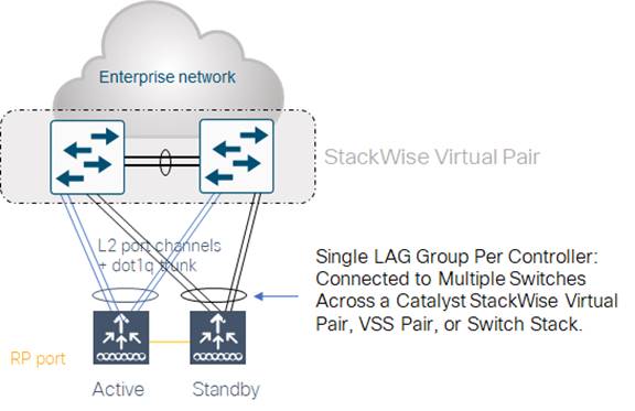
Spreading the ports from the active and standby WLCs across both switches within the Cisco StackWise Virtual pair is the recommended design. This design minimizes the traffic that crosses the virtual switch link between the Cisco Catalyst switches in the Cisco StackWise Virtual pair during normal (non-failure) operation, because both the active and standby WLCs have ports connected to both switches. This design also avoids a switchover from the active WLC to the standby WLC in the event of a switch failure within the pair. However, in the event of a switch failure within the pair, the number of ports connected to the active WLC is reduced by half. You choose a switching platform with appropriate resources to support ARP and MAC address table entries from the wireless controller for the deployed environment.
Note: Catalyst 9800 wireless controllers support PagP and LACP as of IOS XE 17.1 and higher.
Preferred redundancy - Single Cisco Catalyst 9800 controller connected to redundant single logical switch
If you are only connecting a single Cisco Catalyst 9800 controller to the wired LAN, such as for an N+1 controller deployment, connect the single controller physical ports spread across redundant Cisco Catalyst switches in a Cisco StackWise Virtual pair, switch stack, or separate line cards in a highly redundant modular chassis.
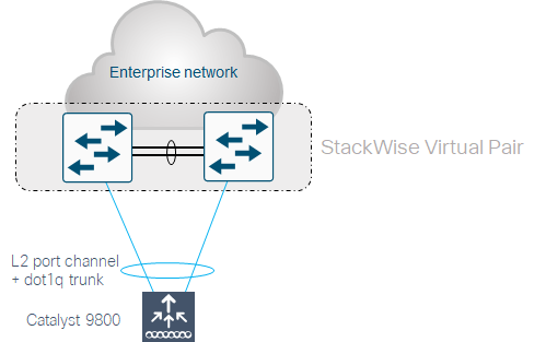
The trunk configuration and switching platform choices from the previous design also apply here.
Wireless controller patches using software maintenance updates (SMUs)
An SMU is a software package that can be installed on a wireless controller to provide a patch fix for bugs or security resolution to an already released image. Cisco Catalyst 9800 Series controllers support two types of SMUs - hot patching and cold patching.
A hot patch does not need a system reload - meaning that clients and APs will not be affected when applying the hot patch. When the wireless controller is part of an HA SSO pair, the SMU activation applies to both the active and standby controllers.
A cold patch does require a system reload. However, in an HA SSO pair, the system will first install the SMU on the standby controller and reload it. Once the standby finishes reloading the active controller will reload. When this happens, a switchover occurs, and the standby controller becomes the new active controller. The new active controller takes over all AP and client sessions. Then, the new standby controller (previously the active controller) is updated. Throughout this update, AP and client sessions remain up.
Note: SMUs are only released on long-lived Cisco IOS-XE extended maintenance releases.
AP patches using Access Point Service Packs (APSPs)
Cisco Catalyst 9800 Series wireless controllers support rolling out critical AP bug fixes using APSPs. APSP rollout can be based upon sites, with the fix predownloaded and rolled out to only affected AP models.
With rolling AP upgrade, AP upgrades can be staggered to ensure RF coverage to clients throughout the upgrade process. Rolling updates support automatic candidate selection using Radio Resource Management (RRM)-based AP neighbor information. Based upon a chosen percentage per iteration (5%, 15% or 25%, with the default being 15%) the wireless controller auto-selects candidate APs to be upgraded in each iteration. Clients from the candidate APs are actively steered away using 802.11v packets with the "disassociation imminent" field set, to help ensure seamless network connectivity as the APs are upgraded. Clients that do not honor this setting are de-authenticated before the AP is reloaded.
Support for new AP models using Access Point Device Packs (APDPs)
Beginning with Cisco IOS-XE release 16.11, Cisco Catalyst 9800 Series wireless controllers provide a way to support new AP models using APDPs. This provides a way to introduce new AP models into your network without having to upgrade the wireless controller software version. Also, since the APDPs are hot patches, they do not require a reload and require no downtime of the wireless controller.
The following table summarizes high availability support with the various controllers.
Table 4. High availability feature support
| Platform |
HA SSO |
N+1 HA |
Stack Redundancy |
LAG |
SMUs, APSPs, and APDPs |
| Cisco Catalyst 9800-80 |
Yes |
Yes |
— |
Yes |
Yes |
| Cisco Catalyst 9800-40 |
Yes |
Yes |
— |
Yes |
Yes |
| Cisco Catalyst 9800-L |
Yes |
Yes |
— |
Yes |
Yes |
| Cisco Catalyst 9800 embedded on Cisco Catalyst 9000 Series Switches |
No |
No |
Yes |
— |
Yes |
| Cisco Catalyst 9800 Embedded on Catalyst 9100 Series Access Points (EWC) |
Active/standby control plane with local switching data plane |
No |
— |
— |
Yes |
| Cisco Catalyst 9800-CL for |
No |
Yes |
— |
— |
Yes |
| Cisco Catalyst 9800-CL for Private Cloud |
Yes |
Yes |
— |
Via hypervisor |
Yes |
Multicast support
Video and voice applications continue to grow as smartphones, tablets, and PCs are added to wireless networks in all aspects of our daily life. In each of the wireless design models, the multicast support to which users are accustomed on a wired network is available wirelessly. Multicast is required in order to enable the efficient delivery of certain one-to-many applications, such as video and push-to-talk group communications. By extending the support of multicast beyond that of the campus and data center, mobile users can now use multicast-based applications.
The campus WLAN supports multicast transmission for the onsite controller using multicast-multicast mode, which uses a multicast IP address in order to more efficiently communicate multicast streams to APs that have wireless users subscribing to a particular multicast group. In this guide, multicast-multicast mode is supported by using the Cisco Catalyst 9800 Series WLAN Controllers.
Remote sites that use Cisco FlexConnect local switching mode can also benefit from the use of multicast-based applications. Multicast in remote sites leverages the underlying WAN and LAN support of multicast traffic. When combined with APs in Cisco FlexConnect mode using local switching, subscribers to multicast streams are serviced directly over the WAN or LAN network with no additional overhead being placed on the WLAN controller.
Guest wireless
Using the existing campus wired and wireless infrastructure for guest access provides a convenient, cost-effective way to offer Internet access for visitors and contractors. Multiple methods of providing guest wireless access are supported, depending on the deployment.
Centralized deployments with guest wireless
For centralized (local-mode) deployments, the traditional method of providing wireless guest access is to implement a dedicated guest anchor controller in an Internet DMZ segment. The internet edge / DMZ firewall restricts access from the guest network (specific ports on the firewall need to be opened for the tunneled data connection). The guest network is only able to reach the Internet and the internal DHCP and DNS servers (unless separate DHCP and DNS servers are deployed within the DMZ for further isolation).
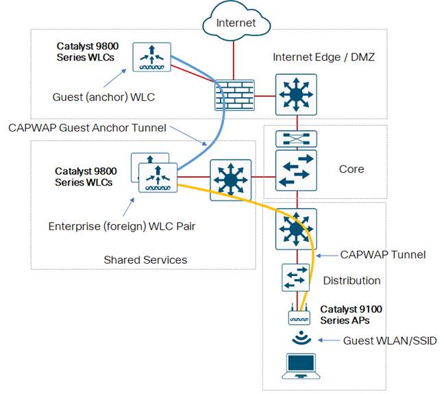
Additional security functionality besides firewalling may be applied within the Internet Edge / DMZ. This additional functionality is not shown in the figure above.
Cisco Catalyst 9800 Series wireless controllers support secure mobility – meaning the anchor tunnel uses CAPWAP encapsulation, as opposed to Ethernet-over-IP (EoIP). CAPWAP control traffic is encrypted, with the additional option of encrypting the CAPWAP data traffic between the foreign and anchor wireless controllers.
Cisco FlexConnect guest deployments
For Cisco FlexConnect guest deployments, the guest WLAN/SSID can be centrally switched and anchored through a dedicated guest controller in an Internet DMZ segment.
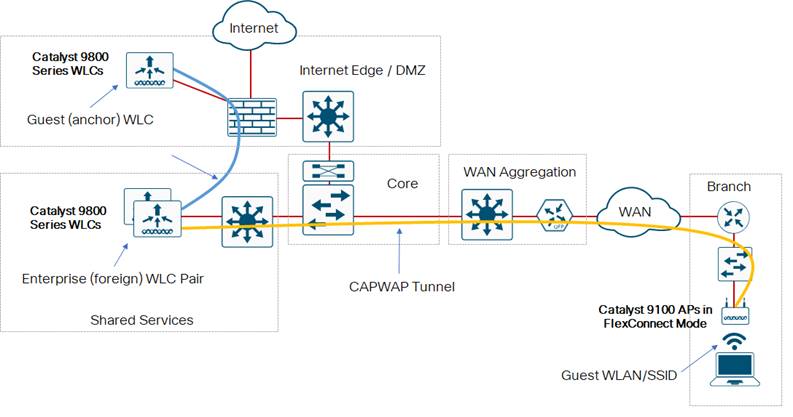
Alternatively, the guest WLAN/SSID can be locally switched to a VLAN within the branch which provides direct Internet access (DIA).
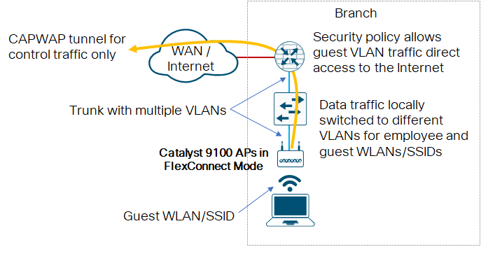
Additional security functionality besides firewalling may be applied within the branch for direct Internet access. This is not shown in the figure above.
Cisco SD-Access deployments with guest wireless
For fabric wireless guest access services to the Internet, you can separate wireless guests from other network services by creating a dedicated virtual network (VN) supporting the guest SSID. Extend the separation of the guest traffic between the fabric border and DMZ using VRF Lite or similar techniques. This type of deployment does not require any dedicated guest anchor controller to be deployed. Alternatively, guest traffic can be encapsulated right from the fabric edge node to the Guest Border/Control Plane node in the DMZ, providing total isolation from enterprise data traffic.
For more information, see the Software-Defined-Access Solution Design Guide, at https://cs.co/sda-sdg.
Cisco Catalyst 9100 Series EWC deployments guest wireless
Cisco Catalyst 9100 Series EWC deployments do not support a dedicated guest anchor wireless controller. As with FlexConnect locally switched deployments, the guest WLAN/SSID can be locally switched to a VLAN within the branch which provides direct Internet access (DIA).
All guest wireless deployments—authentication and access control
Regardless of the wireless deployment option, the wireless guest network typically provides the following functionality:
● Provides Internet access to guests through an open wireless SSID, with web authentication access control.
● Supports the creation of temporary authentication credentials for each guest by an authorized internal user.
● Keeps traffic on the guest network separate from the internal network in order to prevent a guest from accessing internal network resources.
Most organizations’ IT departments choose to have guest wireless users authenticate first, before allowing access to the Internet. This step is sometimes accompanied with the guest user reading and agreeing to an acceptable use policy (AUP) or end-user agreement (EUA) before accessing the Internet. Since the organization’s IT department typically has no control over the hardware or software capabilities of guest wireless devices, the authentication and authorization decision is often based on only a guest userid and password. In other words, the device with which the guest is accessing the network may not be considered for any policy decision. A typical way of implementing guest user authentication is through the guest user’s web browser, a method known as web authentication or WebAuth. With this method of authentication, the wireless guest must first open his or her web browser, or mobile app with embedded browser, to a URL located somewhere within the Internet. The browser session is re-directed to a web portal that contains a login page that requests login credentials. Upon successful authentication, the guest user is either allowed access to the Internet or redirected to another web site. This authentication method is also known as a captive portal.
There are multiple ways of authenticating guests on WLANs, such as the following:
● Local web authentication—With this method, the web session of the guest device is redirected by the guest wireless controller to a web portal containing the login screen within the guest wireless controller. The guest’s credentials are then checked against the local database within the guest wireless controller. The advantage of this option is that the entire management of guest wireless access is confined to the guest wireless controller within the DMZ. The downside of this option is that guest credentials are maintained separately within the guest wireless controller.
● Central web authentication—With this method, the web session of the guest device is redirected by the guest wireless controller to an external web portal containing the login screen. The guest’s credentials are then checked against an external database within an authentication, authorization, and accounting (AAA) server. Cisco Identity Services Engine (ISE) can provide both the external web portal and AAA server functionality. By positioning the web authentication login portal in a central server, the network administrator can provide one unified login page—with an optional AUP or EUA—for all wireless guest access without having to create a separate login page on each guest wireless controller. By moving the guest credential database and guest sponsor portal to an AAA server, the network administrator can provide one central place for creating and managing guest credentials, versus having to create guest credentials on each guest wireless controller.
● Cisco DNA Spaces-based guest onboarding—Cisco DNA Spaces-based guest-onboarding is often implemented by organizations who wish to provide free Internet access within their venue, in exchange for collecting some information from customers who visit the site. With this method, guests can use the wireless network and access the Internet from the venue by logging in using their existing social media credentials. The venue owner may also choose to allow anonymous login to the wireless network. The venue owner may also optionally choose to display a splash page and registration form, customized for that venue location.
Multicast domain name services and Bonjour gateway
Bonjour is Apple’s zero-configuration protocol for advertising, discovering, and connecting to network services such as file sharing, print sharing, and media sharing. The Bonjour protocol was originally designed for home network use and uses multicast domain name services (mDNS) via link-local multicasting to share network services. Although this approach works well in home networks, a limitation of link-local multicasting is that these network services will only be shared within a single Layer 2 domain (such as a VLAN or WLAN). In a WLAN enterprise scenario, you use different WLANs and VLANs for different classes of devices, including corporate devices, employee devices, personal devices, and guest devices (as well as quarantine WLANs for unapproved devices). As such, basic Bonjour operations—such as printing to a wired printer from a WLAN—may not be natively supported.
To address this limitation and to meet user demand for BYOD Apple devices within the enterprise, Cisco developed the Bonjour Gateway feature for its WLCs, in addition to Service Discovery Gateway (SDG) on Catalyst switches and the cisco DNA Service for Bonjour on Cisco DNA Center. The Bonjour Gateway feature for WLCs solves the Layer 2 domain limitation for Bonjour by allowing the WLC to snoop, cache, and proxy-respond to Bonjour service requests that may reside on different Layer 2 domains. Additionally, these responses may be selectively controlled by administrative policies, so that only certain Bonjour services will be permitted in specific Layer 2 domains.
The Bonjour protocol uses mDNS queries. These queries are sent over UDP port 5353 to these reserved group addresses:
● IPv4 Group Address: 224.0.0.251
● IPv6 Group Address: FF02::FB
It is significant to highlight that mDNS addresses used by Bonjour are link-local multicast addresses and are only forwarded within the local Layer 2 domain, because link-local multicast is meant to stay local by design. Furthermore, routers cannot even use multicast routing to redirect the mDNS queries, because the time-to-live (TTL) of these packets is set to the value 1.
This link-local multicast limitation of Bonjour mDNS is illustrated in the following figure.
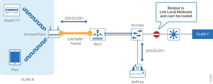
The Bonjour Gateway feature (the mDNS gateway feature most often enabled for Bonjour) snoops and caches all Bonjour service advertisements across multiple VLANs and can be configured to selectively reply to Bonjour queries.
Bonjour gateway service policy deployment options
A key functional advantage of the Bonjour gateway is that it can be configured to selectively reply to Bonjour service requests, thus allowing for administrative control of Bonjour services within the enterprise. For Cisco Catalyst 9800 Series WLCs, Bonjour service policies are applied to Policy Profiles (which include the VLAN to which the WLAN is terminated). Policy Profiles and WLAN Profiles (which include the WLAN/SSID name) are then attached to Policy Tags, which are then attached to APs.
Since the Cisco Catalyst 9800 Series wireless controller will respond and advertise for services cached when acting as a Bonjour gateway, it must have an SVI interface with a valid IP address on every VLAN where mDNS is allowed or used. This will be the source IP address of those mDNS packets that are coming out from the controller acting as mDNS Gateway.
Cisco Application Visibility and Control
The Cisco Application Visibility and Control (AVC) solution —already supported on Cisco routing platforms such as the Cisco ASR 1000 and Cisco ISR, and Cisco switching platforms such as the Cisco Catalyst 9200, 9300, and 9400 Series— is available on WLC platforms, including the Cisco Catalyst 9800 Series WLCs.
The Cisco AVC feature set increases the visibility, productivity, and manageability of the wired and wireless network. Additionally, the support of AVC embedded within the WLAN infrastructure extends Cisco’s application-based QoS solutions end-to-end.
AVC includes these components:
● Next-generation deep packet inspection (DPI) technology called Next Generation Network-Based Application Recognition (NBAR2), which allows for identification and classification of applications. Available on Cisco IOS–XE based platforms, NBAR2 is a deep-packet inspection technology that includes support of stateful L4-L7 classification.
● Ability to remark applications using DSCP policies, which you can then use to prioritize or de-prioritize applications for QoS treatment over both the wired and wireless networks.
● A template for Cisco Flexible NetFlow v9 to select and export data (local-mode only) of interest to Cisco PI or a third-party NetFlow collector to collect, analyze, and save reports for troubleshooting, capacity planning, and compliance purposes.
Cisco AVC on the Cisco Catalyst 9800 Series wireless LAN controllers inherits NBAR2 from Cisco IOS-XE that provides DPI technology in order to classify stateful L4-L7 application classification. This is critical technology for application management because it is no longer a straightforward matter of configuring an access list based on the TCP or UDP port number(s) to positively identify an application. In fact, as applications have matured —particularly over the past decade— an ever-increasing number of applications have become opaque to such identification. For example, HTTP protocol (TCP port 80) can carry thousands of potential applications within it and in today’s networks seems to function more as a transport protocol, rather than as the OSI application-layer protocol that it was originally designed to be. Therefore, to identify applications accurately, DPI technologies such as NBAR2 are critical.
After the NBAR engine recognizes applications by their discrete protocol signatures, it registers this information in a Common Flow Table so that other WLC features, such as Flexible NetFlow and QoS, can leverage this classification result.
Cisco AVC provides:
● Application Visibility on the Cisco Catalyst 9800 Series WLC by enabling Application Visibility for any WLAN wireless policy profile configured. Once you enable Application Visibility, the NBAR engine classifies applications for the configured WLAN. Custom applications are also supported. You can view Application Visibility on the WLC at an overall network level, per WLAN or per client.
● Application Control on the Cisco Catalyst 9800 Series WLC by creating an AVC-based QoS policy and attaching it to a policy profile attached to a WLAN. The QoS policy supports rules per application matched to a traffic-class and provides the following actions to be taken on each traffic-class: mark (with DSCP), police (to a rate), or drop.
Key business use cases for Cisco AVC include:
● Classifying and marking wireless mobile device applications—Identifying and differentiating real-time voice, video, or business-critical applications from less important (but potentially bandwidth-hungry) applications in order to prioritize, de-prioritize, or drop specific application traffic.
● Capacity planning and trending—Baselining the network to gain a clearer understanding of what applications are consuming bandwidth and trending application use in order to help network administrators plan for infrastructure upgrades.
Cisco Catalyst 9800 advanced wireless intrusion prevention system (wIPS)
The Cisco Catalyst 9800 advanced wIPS architecture—available in Cisco IOS-XE 17.1 and higher—provides the following benefits:
● Low footprint solution
● Ease of Cisco DNA licensing (requires Cisco DNA Advantage licensing)
● Alarm consolidation
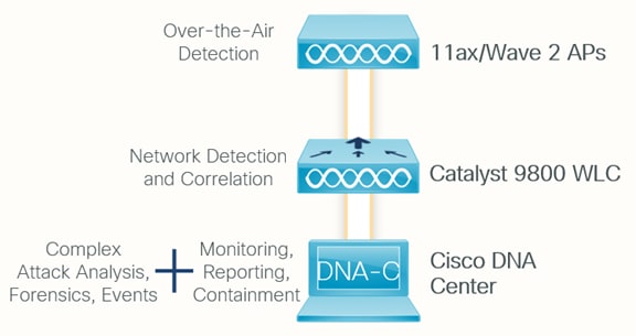
The basic system components for a Cisco Catalyst 9800 adaptive wIPS system include:
● Cisco 802.11ax or 802.11ac Wave 2 APs (local-mode, Cisco FlexConnect mode, or monitor mode)
● Cisco Catalyst 9800 Series Wireless controllers (local-mode, Cisco FlexConnect, or fabric deployments)
● Cisco DNA Center
Table 5. Alarms supported in Cisco IOS-XE 17.1
| Alarm ID |
Alarm |
| 10001 |
DoS: Authentication Flood Alarm |
| 10002 |
DoS: Association Request Alarm |
| 10003 |
DoS: Broadcast Probe Flood Alarm |
| 10004 |
DoS: Dissociation Flood Alarm |
| 10005 |
DoS: Broadcast Dis-Association Alarm |
| 10006 |
DoS: De-Authentication Flood Alarm |
| 10007 |
DOS: Broadcast De-authentication Alarm |
| 10008 |
DOS: EAPOL-Logoff Attack Alarm |
Rogue device detection
An organization can regard any device unmanaged by the organization that shares the organization’s RF spectrum as a rogue device. A rogue device becomes dangerous in the following scenarios:
● Rogue AP with the same SSID as your network (often called a honeypot)
● Rogue AP device also on the wired network
● Ad-hoc rogue devices
● Rogue devices set up for malicious intent by someone outside the organization
There are three main phases of rogue device management in the Cisco Catalyst wireless solution:
● Detection—Managed using RRM scanning in order to detect the presence of rogue devices.
● Classification—Managed using rogue location discovery protocol (RLDP) and switch port tracing in order to identify whether the rogue device is connected to the wired network. Rogue device classification rules also assist in filtering rogue devices into specific categories based on the characteristics of a device.
● Mitigation—Managed using switch port tracing and disablement, rogue device location, and rogue device containment in order to track down physical location and nullify the threat of rogue devices.
Cisco DNA Center release 1.3.1.3 and higher supports the Rogue Management application within Cisco DNA Assurance. The Rogue Management application allows you visualize rogue APs as well as their potential threat level (informational, potential, or high) from within Cisco DNA Center.
For additional information about a range WLAN controller versions, visit cisco.com and search for "Wireless Rogue Management."
Radio Resource Management (RRM)
To optimize efficiency, RRM software embedded in the Cisco Wireless LAN Controller acts as a manager to constantly monitor over-the-air metrics and control the RF transmitted. It measures:
● Signal—Your own APs belonging to the same RF network.
● Interference—Other 802.11 devices operating nearby that can be heard by your network.
● Noise—Any energy in the RF spectrum that cannot be demodulated as 802.11 protocol.
● Load—Instantaneous user load on the network.
● Coverage—The RSSI and signal-to-noise ratio estimated by the system for clients attached to your network.
Using this information, RRM can periodically reconfigure the 802.11 RF network for best efficiency. To do this, RRM performs these functions:
● RRM data collection—Collecting the metrics
● Transmit Power Control (TPC) algorithm—Adjusting for optimal power levels
● Dynamic channel assignment (DCA)—Ensuring that channel assignments do not overlap
● Cisco Flexible Radio Assignment (FRA)—Determines the role of the flexible radio for APs with that flexible radio capability
● Coverage Hole Detection and Mitigation (CHDM) algorithm—Ensuring that you have adequate coverage and detecting clients that may be in a coverage hole
RRM automatically detects and configures new Cisco WLCs and Cisco Catalyst APs as they are added to the network. It then automatically adjusts associated and nearby APs to optimize coverage and capacity.
For more detailed information about what RRM does and how it takes its measurements, see the Radio Resource Management White Paper on cisco.com.
Transmit power control
The Cisco WLC dynamically controls AP transmit power based on real-time WLAN conditions. Cisco Catalyst 9800 Series WLCs support TPCv1 only. With TPCv1, typically power can be kept low to gain extra capacity and reduce interference. TPCv1 is well suited for use in most deployments.
Overriding the TPC algorithm with minimum and maximum transmit power settings
The TPC algorithm balances RF power in many diverse RF environments. However, it is possible that automatic power control will not be able to resolve some scenarios in which an adequate RF design was not possible to implement due to architectural restrictions or site restrictions—for example, when all APs must be mounted in a central hallway, placing the APs close together but requiring coverage out to the edge of the building.
In these scenarios, you can configure maximum and minimum transmit power limits to override TPC recommendations. The maximum and minimum TPC power settings apply to groups of APs through the use of RF profiles within RF tags. When used as a global configuration option, the settings apply to all APs attached to the specific controller.
If you configure a minimum transmit power, RRM does not allow any AP attached to the controller to go below this transmit power level, regardless of which function is directing the power change (RRM TPC or coverage hole detection). For example, if you configure a minimum transmit power of 11 dBm, then no AP will transmit below 11 dBm, unless the AP is configured manually and no longer under control of RRM.
Dynamic Channel Assignment
The 802.11 specification defines multiple channels for operation. The channels are essentially different frequency ranges that are non-overlapping and can be assigned using a channel designator. The behavior is analogous to lanes on a highway—you only get the full benefit of the lane if it is completely separate from another lane on the same highway. If the lanes overlap each other (or worse, merge into a single lane), then the highway slows to a crawl.
Channels in an RF network work similarly. However, there is an additional consideration of power, equivalent to making lane wider or narrower (the coverage of the AP). The job of Dynamic Channel Assignment is to track the available lanes (channels), which differ by regulations depending on the country of installation. Secondly, DCA assigns channels to APs that do not conflict with channels already assigned. For a given AP, potential throughput is dependent upon interference free operation. DCA is aware of what channels on which you are allowed to operate and assigns these channels to be as interference-free as possible, based on over-the-air observations.
After all APs have been installed, it is a best practice to then calibrate DCA by invoking the RRM start-up mode. The RRM startup mode is invoked in the following conditions:
● In a single-controller environment, the RRM startup mode is invoked after a successful upgrade of the controller software; otherwise, it is manually initiated (see below).
● In a multiple-controller environment, the RRM startup mode is invoked after an RF Group leader has successfully upgraded the software; otherwise, it is manually invoked from the CLI.
You can trigger RRM startup mode from CLI, using the following command:
ap dot11 {24ghz | 5ghz} rrm dca restart
RRM startup mode runs for 100 minutes (10 iterations at 10-minute intervals). The startup mode consists of 10 DCA runs with high sensitivity and no dampening (making channel changes easy and sensitive to the environment) to converge to a steady state channel plan. After the startup mode is finished, DCA continues to run at the interval and sensitivity as specified by the organization.
Cisco Flexible Radio Assignment
Cisco FRA is a feature that takes advantage of hardware choices available in the Cisco Catalyst 9100 Series APs. As described for band selection, there are limitations using the 2.4 GHz spectrum. If you are deploying APs for optimal 5 GHz coverage and density, you will likely have an unnecessarily high density of 2.4 GHz radios and their limited channel selection options, which will cause interference issues. Cisco FRA measures this and identifies APs whose 2.4 GHz radio can be selectively assigned to a role that optimizes the use of the RF spectrum.
Cisco FRA first identifies redundant APs and then manages the changing of the single XOR radio to another band. Cisco FRA relies on hardware capabilities as well as existing DCA in order to manage the switching of interface roles. Cisco FRA also provides a new metric, Coverage Overlap Factor, that admins can use to manually select and configure redundant radios within the deployment.
Coverage Hole Detection and Mitigation algorithm
The RRM CHDM algorithm detects areas of weak radio coverage in a WLAN that are below the level needed for robust radio performance. This feature can alert you to the need for an additional or relocated AP.
If clients associated to an AP are detected at threshold levels lower than those specified in the RRM configuration, the AP sends a “coverage hole” alert to the controller. The thresholds include RSSI, failed client count, percentage of failed packets, and number of failed packets. The alert indicates the existence of an area where clients are continually experiencing poor signal coverage without having a viable AP to which to roam. The controller discriminates between coverage holes that can and cannot be corrected. For coverage holes that can be corrected, the controller mitigates the coverage hole by increasing the transmit power level for a specific AP that can improve the coverage. For clients that are making poor roaming decisions (referred to as sticky clients), the CHDM algorithm reports a false positive. System validation ensures that a client really does have better coverage on the new AP and is not just unnecessarily moving to that new AP for an arbitrary reason.
Benefits of RRM
RRM produces a network with optimal capacity, performance, and reliability. It frees you from having to continually monitor the network for noise and interference problems, which can be transient and difficult to troubleshoot. RRM ensures that clients enjoy a seamless, trouble-free connection throughout the Cisco wireless network.
Band Select
Most consumer devices being released today operate in one or both of two frequency ranges, or, bands. Dual-band devices are quite common; however, the bands supported by the devices are not created equally. The properties and number of frequencies available for 2.4 GHz and 5 GHz devices differ significantly, with 5 GHz having as much as 8 times the available bandwidth as 2.4 GHz. Even so, the 2.4 GHz physical properties allow a device to be heard much further (1.5 times as much) than 5 GHz devices operating at the same power level.
Band Select allows identification of dual-band clients and helps the devices make informed decisions about which frequency range and AP to select. The system does this by simply delaying the response to the 2.4 GHz probes from a client and by immediately answering the client when the client uses 5 GHz probes. This system behavior encourages clients to use the available superior bandwidth in 5 GHz and increases the overall network capacity.
Organizations are advised to enable Band Select in all environments. For more information on configuring Band Select, visit cisco.com and search for Wireless Controller Configuration 802.11 Bands.
Dynamic bandwidth selection (DBS)
With the introduction of 802.11n, 802.11ac Wave 1 and Wave 2, and 802.11ax, you can use multiple channels together as a single assignment on a given AP. This increases the amount of bandwidth available for a given channel and improves the throughput and apparent speed perceived by the client. However, to use these combined channels, an AP and a client must both support the capability.
Bonding channels—using multiple single channels to create a single super channel—has the advantage of providing more usable throughput to a client with the capability to use the channel. However, in grouping multiple channels to create a single channel, larger slices of the spectrum are consumed, decreasing the overall number of non-interfering channels to use with DCA. This can result in aggressive channel reuse if there are enough APs (each one requires an operating channel) and increased co-channel interference, counter to the intended goal of throughput efficiency.
Dynamic Bandwidth Selection works with the DCA algorithm to monitor the APs and the client types and capabilities using the APs. Based on this analysis, DBS assigns appropriate channel widths to APs to dynamically balance the bandwidth selection for the types of clients and traffic that each AP uses.
DBS allows appropriately sized bandwidth to be used for the clients being served, avoids wasting multiple channels for devices that likely could not use the added capacity, and avoids the associated interference created by those devices. For these reasons, you should run DCA in DBS mode.
For additional details, visit cisco.com and search for High Density Experience (HDX) Deployment Guide.
Cisco CleanAir
Cisco CleanAir is a purpose-built spectrum intelligence solution designed to proactively manage the non-Wi-Fi interference in the 2.4 and 5 GHz spectrums. Many consumer devices use the same frequencies that are used for 802.11 Wi-Fi—Bluetooth headsets, microwave ovens, and many new IOT devices use different protocols but occupy the same frequencies required for operation of the WLAN.
Cisco CleanAir is an innovation available in Cisco Catalyst 9120AX and 9130AX APs, which include the Cisco RF ASIC. CleanAir is dedicated to detecting and identifying sources of interference that otherwise would simply appear as noise to a Wi-Fi chipset.
Cisco CleanAir technology was released in 2010 and has continuously adapted to keep pace with the market and changing nature of the WLAN spectrum. CleanAir monitors the full channel bandwidth capability of a CleanAir-capable AP regardless of the deployment requirements, and as a result, it monitors the range of 20 MHz-160 MHz channels.
CleanAir can report analysis and findings through the WLAN controller. You can use certain Cisco DNA Spaces implementations and Cisco Prime to map both the interference and the impact of the interference for easy analysis and troubleshooting.
At the controller level, you can use two mitigation strategies to help maintain your network and prevent outages associated with common non-Wi-Fi interference sources:
● Persistent Interference Avoidance—Allows the WLC to track and report non-Wi-Fi interferers to DCA. For instance, there may be a microwave oven that becomes quite active around lunchtime every day. Persistent Interference Avoidance remembers this device and instructs DCA to pick channels for the affected APs that will not be interfered with by this periodic interference source.
● ED-RRM—Helps mitigate disruptions from interference sources (perhaps a video camera) that use 100% of the available airtime when enabled. Because this interference is not recognizable as anything other than noise to the 802.11 chipset, all clients and APs typically wait for the channel to become less busy. ED-RRM provides a safety net by doing two things:
◦ Recognizing that something is not noise but instead is intentionally transmitting and interfering with the network operations.
◦ Forcing the AP away from the problematic channel to a channel where operations can resume. The resolution is very fast acting (30 seconds or less), and the information about the interference is incorporated into RRM through DCA, alerting DCA about interference disruptions related to the channel just abandoned.
As a best practice, you should enable CleanAir, Persistent Device Avoidance, and ED-RRM.
For additional details, visit cisco.com and search for the Cisco CleanAir Technology: Intelligence in Action White Papers.
Secure WLANs
Wireless devices should connect to the network infrastructure securely where possible. In an enterprise environment, secure the WLANs by configuring at least WPA2 with AES-CCMP encryption, and 802.1x authentication of devices. This is sometimes referred to as WPA Enterprise on wireless devices. Most modern wireless devices support WPA2. You should consider migrating to the newer WPA3 standard, which is supported by Cisco Catalyst 9800 Series wireless controllers.
WPA3 is the latest version of Wi-Fi Protected Access (WPA), which is a suite of protocols and technologies that provide authentication and encryption for Wi-Fi networks. WPA3 leverages Simultaneous Authentication of Equals (SAE) to provide stronger protections for users against password guessing attempts by third parties. SAE employs a discrete logarithm cryptography to perform an efficient exchange in a way that performs mutual authentication using a password that is probably resistant to an offline dictionary attack. Adversaries use offline dictionary attacks in attempts to determine a network password by trying possible passwords without further network interaction.
WPA3-Personal protects individual users better by using more robust password-based authentication making the brute-force dictionary attack much more difficult and time-consuming. WPA3-Enterprise provides higher grade security protocols for sensitive data networks.
Opportunistic Wireless Encryption (OWE) is an extension to IEEE 802.11 that provides encryption of the wireless medium. The purpose of OWE based authentication is avoid open unsecured wireless connectivity between the APs and clients. The OWE extension uses the Diffie-Hellman algorithm cryptography to setup the wireless encryption. With OWE, the client and AP perform a Diffie-Hellman key exchange during the access procedure and use the resulting pairwise secret with the 4-way handshake. The use of OWE enhances wireless network security for network deployments using open or shared PSK.
The use of older security methods, such as WEP or WPA, is not recommended due to known security vulnerabilities. 802.1x authentication requires an AAA server—such as Cisco ISE—that provides centralized policy-based management and control for end-users accessing the wireless network.
Typically, the AAA server will implement the RADIUS protocol between itself and the WLC. Authentication of end-users is accomplished via an extensible authentication protocol (EAP) session between the wireless device and the AAA server. The EAP session is transported via RADIUS between the WLC and the AAA server. Depending upon the capabilities of wireless device, the capabilities of the AAA server, and the security requirements of the organization, multiple variants of EAP, such as PEAP and EAP-TLS, may be implemented. PEAP makes use of standard user credentials (userid & password) for authentication. EAP-TLS makes use of digital certificates for authentication.
It is highly recommended that you deploy redundant AAA servers for high availability in case one or more servers become temporarily unavailable. Often the AAA server is configured to reference an external directory or data store such as Microsoft’s Active Directory (AD). This allows the network administrator to leverage existing AD credentials instead of duplicating them within the AAA server. This can also be extended to provide role-based access control (RBAC) for end-users through the use of AD groups. For example, it may be desirable to provide restricted network access to long-term contractors, as opposed to the access granted employees. The use of an external directory or data store can also provide a single point for granting or revoking credentials, not only for access to the network infrastructure, but for access to other resources within the organization. The AAA server itself can apply additional policy-based rules for authorization to the network, such device type, time of day, location, etc., depending upon the capabilities of the AAA server. AAA logs and accounting may be used to provide an audit trail of each employee’s access to the wireless network infrastructure.
The use of WPA2 with AES-CCMP encryption on the WLAN does not extend to management frames. Therefore, the optional use of protected management frames (PMF) is advisable for WLANs where possible. PMF is part of the IEEE 802.11 standard, which provides a level of cryptographic protection to robust management frames such as de-authentication and dissociation frames, preventing them from being spoofed. It should be noted that the benefits of PMF does require wireless clients to support PMF. Cisco also offers an earlier version of Management Frame Protection (MFP) that has both infrastructure and client components.
In a home-office environment, it may be necessary to configure a WLAN to support WPA2 with pre-shared key (PSK). This is sometimes referred to as WPA Personal on wireless devices. This may be necessary because the implementation of an AAA server is not cost-effective for the number of end-users who access the WLAN. This may also be necessary in other environments if there is no end-user associated with a wireless device, the wireless device does not support the ability to configure a userid & password, or the wireless device cannot support a digital certificate. Since the PSK is shared among all devices that access the wireless infrastructure, it may be necessary to change the PSK if an employee who knows the PSK leaves the organization. Furthermore, with WPA PSK, there is no easy audit trail of each employee’s access to the network.
The use of a dedicated, open WLAN is still common, but not ideal, for wireless guest access. Therefore, the configuration of an unsecure WLAN on the network infrastructure may still be necessary. Open access guest WLANs are often implemented in order to minimize the complexity of onboarding a guest who needs only temporary wireless network connectivity. Typically, the guest WLAN is terminated outside the corporate firewall, which allows no access inbound to corporate resources, so guests may be allowed access to the Internet only. Depending upon the requirements of the organization, guests may be required to authenticate before being allowed to access the Internet. Typically, a captive-portal model is used with WebAuth, in which guest web sessions are redirected to a portal, which authenticates the guest before allowing Internet access.
Administrative Access Control
It is recommended that you implement secure administrative access control to wireless infrastructure components in order to mitigate against unauthorized access. You can typically implement administrative access control via the local user database in each infrastructure device, or via a centralized AAA server—such as Cisco ISE.
For a small number of network infrastructure devices, configuring individual local administrator accounts on each infrastructure device may be acceptable. It is recommended that the number of administrators be limited and that each administrator have a unique account. A shared administrator account limits the ability to audit who accessed a particular network device and potentially made configuration changes. When employees leave the organization, or move to other groups, their administrative access should be immediately revoked. With individual administrator accounts, only the account for the particular employee needs to be revoked.
As the number of infrastructure devices within the network grows, the administrative burden of configuring individual local administrator accounts on each infrastructure device can become unmanageable. It is therefore recommended that you control administrative access via an AAA server, which provides centralized policy-based management and control. It is recommended that you deploy redundant AAA servers for high availability in case one or more servers become temporarily unavailable. Network administrators may still configure an individual local administrator account on each infrastructure device for local access via the console port, should all network access to the infrastructure device be lost.
The AAA server may itself reference an external directory or data store such as AD. This allows the network administrator to leverage existing AD credentials instead of duplicating them within the AAA server. This can also be extended to provide RBAC for administrators through the use of AD groups. The use of an external directory or data store can also provide a single point to grant or revoke credentials, not only for administrative access control to multiple infrastructure devices, but for access to other resources within the organization.
Where possible, the selection of a strong password—consisting of a minimum length, and combination of letters, numbers, and/or special characters—should be enforced. Where possible, a maximum number of unsuccessful attempts to access the device, before the account is disabled for a period of time, should also be enforced. Successful and unsuccessful attempts should be logged either locally or to a central logging server. This helps mitigate against (and/or alert appropriate network operations staff about) brute force attempts to gain access to infrastructure devices. Where multiple levels of administrative access are supported, it is recommended you enforce them, with administrators having the minimum access level required for performing their respective tasks. It is also recommended that you limit the number of concurrent logins from a single username.
It may be advantageous to limit where access to the wireless infrastructure device is initiated from and what protocols are allowed. You can accomplish this in multiple ways. For example, you can deploy the management interface of WLAN controllers on a separate VLAN (and therefore a separate IP subnet) from wireless client traffic. In such a deployment, an access-control list (ACL) deployed on the Layer 3 switch adjacent to the WLAN controller can limit access to the management interface. This shifts the CPU burden of an ACL off the WLAN controller to the Layer 3 switch. Alternatively, you can configure a CPU ACL on the WLAN controller to filter management protocols. You can also disallow management of the WLAN controller via a wireless device, a method that may also provide additional security if the intention is to manage the wireless infrastructure from a central network operations center.
Access to wireless infrastructure devices should be via secure protocols such as HTTPS and SSHv2 where possible. Access via non-encrypted protocols such as HTTP and Telnet should be disabled where possible. This protects the confidentiality of the information within the management session. When using SNMP, it is recommended that you enable SNMPv3 where possible. SNMPv2c relies on a shared community string that is sent in clear text across the network. Take caution when using SNMPv2c, particularly when using SNMP for read/write access. SNMPv3 uses unique credentials (userid/password) and can also provide encryption and data authentication services to SNMP traffic.
Controller dashboard best practices checklist
For convenience of network deployment engineers, a best practices checklist is available within the dashboard for WLAN controllers. On Cisco Catalyst 9800 Series wireless controllers, the checklist separates best practices into four broad categories: infrastructure, security, RF management, and Apple devices. The checklist is used to fine tune WLC configuration to match the best practices as suggested by Cisco. The checklist compares the local configuration on the controller with recommended best practices and highlights all of the features that differ. The check also provides a simple configuration panel to turn on the best practices. Use of best practices is highly recommended for a WLAN deployment involving WLCs.
Deployment Platform Choices: Campus Wired and Wireless LAN
An organization chooses from the spectrum of switching and wireless platforms based on the needs of capacity, capabilities, and compliance. For easy reference, the platform choices shown are grouped by overall network size.
Small-site campus design
The small-site campus design is a single 24 or 48-port access switch or single access switch stack. The demands in the access layer for wired ports and WLAN devices typically number in the dozens (versus the hundreds in the medium design), with requirements for less than 25 APs. The preferred design strives to minimize cost with minimal numbers of components and features offered, though advanced and mission critical options are available choices for networks that require these capabilities.
Campus wired access and wireless access
In the small-site campus design, you make choices for the wired access with a bias towards size and flexibility in order to accommodate the space and power requirements of small sites. Densities and advanced software feature capabilities are not as strong of a requirement, so options with the most economical preference are shown.
Table 6. Small campus suggested deployment platforms (single-tier network)
|
|
Enterprise Class—base foundation network capabilities |
Advanced—foundation plus additional network capabilities |
Mission Critical—Best in class network capabilities |
| Access switches |
Cisco Catalyst 9200 and 9200-L Series |
Cisco Catalyst 9300 and 9300-L Series |
Cisco Catalyst 9404R Switch |
| WLAN controller |
Cisco Catalyst 9800 Embedded on Catalyst 9100 Series Access Points (EWC) or Cisco Catalyst 9800-CL |
Cisco Catalyst 9800-L HA SSO pair or N+1 or Cisco Catalyst 9800-CL |
Cisco Catalyst 9800-L HA SSO pair |
| APs |
Cisco Catalyst 9115AX or 9117AX Series |
Cisco Catalyst 9120AX Series |
Cisco Catalyst 9130AX Series |
| Key capabilities—wired |
Gigabit Ethernet access |
Gigabit Ethernet services, MACsec, TrustSec NetFlow, PoE+ |
Gigabit Ethernet services, MACsec, TrustSec NetFlow, UPOE |
| Key capabilities—wireless |
Wi-Fi 6 (802.11ax), OFDMA, Uplink/Downlink MU-MIMO, BSS Coloring, Target Wake Time (TWT), Apple Features mGig, Cisco CleanAir, Three radios: 2.4 GHz (4x4), 5 GHz (4x4)or(8x8), and BLE |
Wi-Fi 6 (802.11ax), Cisco RF ASIC, Uplink/Downlink OFDMA, MU-MIMO, BSS Coloring, Target Wake Time (TWT), Intelligent Capture, Container support for applications, Apple Features mGig, Cisco CleanAir, HDX, FRA, Four radios: 2.4 GHz (4x4), 5 GHz (4x4), Cisco RF ASIC, and BLE/IoT hardware capable |
Wi-Fi 6 (802.11ax) certified, Cisco RF ASIC, Uplink/Downlink OFDMA, Uplink/Downlink MU-MIMO, BSS Coloring, Target Wake Time (TWT), Intelligent Capture, Container support for applications, Apple Features mGig, Cisco CleanAir, HDX, FRA, Four radios: 2.4 GHz (4x4), 5 GHz (8x8 and 4x4), Cisco RF ASIC, and BLE/IoT hardware capable |
Medium-density campus design
The medium-density campus design adds a single distribution layer to the access layer, which can be standalone or used as a collapsed core connected to another distribution, or other services, or perhaps connected to WAN router at a remote site that has grown large enough to need an aggregation layer. The demands in the access layer for wired ports and WLAN devices typically number in the hundreds versus the thousands for a large design, with requirements for less than a few groups of 50 or fewer APs. The preferred design strives for typical business continuity needs not requiring every redundant component offered and standard network capabilities.
Campus wired distribution, wired access, and wireless
You make choices for the wired distribution and access with a bias towards size and flexibility in order to accommodate the space and power requirements of medium sized installations in a way that can elastically expand as an organization grows. Where densities and advanced software feature capabilities are not as strong of a requirement, options with a more economical and common sparing preference are shown.
The medium-density designs are equivalent to the small-site campus design with the addition of a distribution layer.
Table 7. Medium campus suggested deployment platforms (two-tier network)
|
|
Enterprise Class—base foundation network capabilities |
Advanced—foundation plus additional network capabilities |
Mission Critical—Best in class network capabilities |
| Distribution/aggregation switches |
Cisco Catalyst 9400 Series |
Cisco Catalyst 9500 Series |
Cisco Catalyst 9600 Series |
| Access switches |
Cisco Catalyst 9200 and 9200-L Series |
Cisco Catalyst 9300 and 9300-L Series |
Cisco Catalyst 9400 Series |
| WLAN controller |
Cisco Catalyst 9800-40 or Cisco Catalyst 9800-CL |
Cisco Catalyst 9800-40 HA SSO pair or N+1 |
Cisco Catalyst 9800-40 HA SSO pair |
| APs |
Cisco Catalyst 9115AX or 9117AX Series |
Cisco Catalyst 9120AX Series |
Cisco Catalyst 9130AX Series |
| Key capabilities—wired |
1/10 Gigabit Ethernet services, MACsec, TrustSec NetFlow |
1/10 Gigabit Ethernet services, MACsec, TrustSec NetFlow, UPOE |
1/10/40 Gigabit Ethernet services, MACsec, TrustSec, NetFlow, UPOE |
| Key capabilities—wireless |
Wi-Fi 6 (802.11ax), OFDMA, Uplink/Downlink MU-MIMO, BSS Coloring, Target Wake Time (TWT), Apple Features mGig, Cisco CleanAir, Three radios: 2.4 GHz (4x4), 5 GHz (4x4)or(8x8), and BLE |
Wi-Fi 6 (802.11ax), Cisco RF ASIC, Uplink/Downlink OFDMA, MU-MIMO, BSS Coloring, Target Wake Time (TWT), Intelligent Capture, Container support for applications, Apple Features mGig, Cisco CleanAir, HDX, FRA, Four radios: 2.4 GHz (4x4), 5 GHz (4x4), Cisco RF ASIC, and BLE/IoT hardware capable |
Wi-Fi 6 (802.11ax) certified, Cisco RF ASIC, Uplink/Downlink OFDMA, Uplink/Downlink MU-MIMO, BSS Coloring, Target Wake Time (TWT), Intelligent Capture, Container support for applications, Apple Features mGig, Cisco CleanAir, HDX, FRA, Four radios: 2.4 GHz (4x4), 5 GHz (8x8 and 4x4), Cisco RF ASIC, and BLE/IoT hardware capable |
High-density large campus design
The high-density large campus design has multiple distribution layers connected to a core layer and dense demands in the access layer for wired ports and WLAN devices. You may select this design for cases where densities may not be as high as supported; however, the requirements dictate needs for critical business continuity or advanced capabilities.
Campus core
If there are three or more interconnected distributions or requirements for connectivity at a common location, you use a Layer 3 LAN core in order to simplify the connectivity and management. You use one of the two core options in order to meet the core needs in the high-density large campus design. The flagship platforms for these options:
● Cisco Catalyst 9600 Series—The lead high-density modular platform choice.
● Cisco Catalyst 9500 Series—The lead lower-density fixed platform choice.
Campus wired distribution, wired access, and wireless
In the high-density large campus, you make choices for the wired distribution and access based on the most highly available platforms for the role, the highest density and widest selection of interface options, redundant power and modular control plane, with the most advanced software feature capabilities.
In the high density large campus design, centralized wireless is the preferred option, using APs with 802.11ac Wave 2 and CleanAir capabilities.
Table 8. High-density large campus suggested deployment platforms (three-tier network)
|
|
Enterprise Class—base foundation network capabilities |
Advanced—foundation plus additional network capabilities |
Mission Critical—Best in class network capabilities |
| Core switches |
Cisco Catalyst 9500 Series |
Cisco Catalyst 9600 Series |
Cisco Catalyst 9600 Series |
| Distribution/aggregation switches |
Cisco Catalyst 9400 Series |
Cisco Catalyst 9500 Series |
Cisco Catalyst 9600 Series |
| Access switches |
Cisco Catalyst 9200 and 9200-L Series |
Cisco Catalyst 9300 and 9300-L Series |
Cisco Catalyst 9400 Series |
| WLAN controller |
Cisco Catalyst 9800-80 |
Cisco Catalyst 9800-80 HA SSO pair |
Cisco Catalyst 9800-80 HA SSO pair |
| APs |
Cisco Catalyst 9115AX or 9117AX Series |
Cisco Catalyst 9120AX Series |
Cisco Catalyst 9130AX Series |
| Key capabilities—wired |
1 Gigabit Ethernet access, PoE+ |
1/10/40 Gigabit Ethernet services, MACsec, TrustSec MPLS, NetFlow, UPOE |
Highest availability 1/10/40/100 Gigabit Ethernet services, MACsec, TrustSec MPLS, NetFlow, UPOE |
| Key capabilities—wireless |
Wi-Fi 6 (802.11ax), OFDMA, Uplink/Downlink MU-MIMO, BSS Coloring, Target Wake Time (TWT), Apple Features mGig, Cisco CleanAir, Three radios: 2.4 GHz (4x4), 5 GHz (4x4)or(8x8), and BLE |
Wi-Fi 6 (802.11ax), Cisco RF ASIC, Uplink/Downlink OFDMA, MU-MIMO, BSS Coloring, Target Wake Time (TWT), Intelligent Capture, Container support for applications, Apple Features mGig, Cisco CleanAir, HDX, FRA, Four radios: 2.4 GHz (4x4), 5 GHz (4x4), Cisco RF ASIC, and BLE/IoT hardware capable |
Wi-Fi 6 (802.11ax) certified, Cisco RF ASIC, Uplink/Downlink OFDMA, Uplink/Downlink MU-MIMO, BSS Coloring, Target Wake Time (TWT), Intelligent Capture, Container support for applications, Apple Features mGig, Cisco CleanAir, HDX, FRA, Four radios: 2.4 GHz (4x4), 5 GHz (8x8 and 4x4), Cisco RF ASIC, and BLE/IoT hardware capable |
Operate: Common Components in Campus Designs
Device management using Cisco ISE
Without a centralized access and identity policy enforcement point, it's difficult to ensure the reliability of a network as the number of network devices and administrators increases.
Cisco ISE operates as a centralized AAA server that combines user authentication, user and administrator access control, and policy control in a single solution. Cisco ISE uses a rule-based policy model, which allows for security policies that grant access privileges based on many different attributes and conditions in addition to a user’s identity.
The capabilities of Cisco ISE coupled with a AAA configuration on the network devices reduce the administrative issues that surround having static local account information on each device. Cisco ISE can provide centralized control of authentication, which allows the organization to quickly grant or revoke access for a user on any network device.
Rule-based mapping of users to identity groups can be based on information available in an external directory or an identity store such as Microsoft Active Directory. Network devices can be categorized in multiple device groups, which can function as a hierarchy based on attributes such as location, manufacturer, or role in the network. The combination of identity and device groups allows you to easily create authorization rules that define which network administrators can authenticate against which devices.
These same authorization rules allow for privilege-level authorization, which can be used to give limited access to the commands on a device. For example, a rule can give network administrators full access to all commands or limit helpdesk users to monitoring commands.
Cisco DNA Center
As networks and the number of services they support continue to evolve, the responsibilities of network administrators to maintain and improve their efficiency and productivity also grow. Using a network management solution can enable and enhance the operational efficiency of network administrators.
Cisco DNA Center is a controller for planning, preparation, installation, and integration. Cisco SD-Access is one of the many software application packages that run on DNA Center.
Cisco DNA Center centrally manages major workflow areas, including:
● Design—Configures device global settings, network site profiles for physical device inventory, DNS, DHCP, IP addressing, software image management, plug-and-play, and user access.
● Policy—Defines business intent for provisioning into the network, including creation of virtual networks, assignment of endpoints to virtual networks, and policy contract definition for groups.
● Provision—Provisions devices for management and creates fabric domains, control plane nodes, border nodes, edge nodes, fabric wireless, local-mode wireless, and external connectivity.
● Assurance—Enables health scores dashboard, client/device 360° views, node, client, and path traces.
Cisco DNA Center supports integration using APIs. For example, Infoblox IP address management and policy enforcement integration with ISE are available through DNA Center. A comprehensive set of northbound REST APIs enables automation, integration, and innovation.
● All controller functionality is exposed through northbound REST APIs.
● Organizations and ecosystem partners can easily build new applications.
● All northbound REST API requests are governed by the controller RBAC mechanism.
Cisco DNA Center is key to enabling automation of device deployments into the network providing the speed and consistency required for operational efficiency. Organizations using Cisco DNA Center can benefit from lower cost and reduced risk when deploying and maintaining their networks.
Cisco Prime Infrastructure
Cisco Prime Infrastructure is a sophisticated network management tool that can help support the end-to-end management of network technologies and services that are critical to the operation of your organization; it aligns network management functionality with the way that network administrators do their jobs. Cisco Prime Infrastructure provides an intuitive, web-based GUI that can be accessed from anywhere from within the network and gives you a full view of a network use and performance.
With a campus network and the services that it can support, Cisco Prime Infrastructure can play a critical role in day-to-day network operations.
Device Work Center
Cisco Prime Infrastructure includes the Device Work Center. Some of the features found in the Device Work Center are:
● Discovery—Builds and maintains an up-to-date inventory of managed devices, including software image information and device configuration details.
● Configuration Archives—Maintains an active archive of multiple iterations of configuration files for every managed device.
● Software Image Management—Enables a network administrator to import software images from Cisco.com, managed devices, URLs, or file systems, and then distribute them to a single device or group of devices.
Configuration Templates and Tasks
Using the Configuration Tasks feature to apply configuration templates to many devices, administrators can save many hours of work. Cisco Prime Infrastructure provides a set of templates and you can use them to create a configuration task, providing device-specific values as needed. For other configuration needs, Cisco Prime Infrastructure enables you to define your own templates.
Alarms, Events, and Syslog Messages
Cisco Prime Infrastructure provides the Alarms and Events feature, which is a unified display with detailed forensics. The feature provides actionable information and the ability to automatically open service requests with the Cisco Technical Assistance Center.
Reporting
Cisco Prime Infrastructure provides you a single launch point for all reports that you can configure, schedule, and view. The Report Launch Pad page provides access to over 100 reports, each of which you can customize as needed.
Cisco CleanAir support
Cisco Prime Infrastructure supports the management of CleanAir enabled wireless APs, enabling administrators to see interference events.
Network Analysis Module support
For increased visibility into your network, Cisco Prime Infrastructure supports management and reporting for Cisco Network Analysis Module products.
Cisco Prime Infrastructure and Cisco DNA Center choices for WLAN deployments
The following are recommendations when deciding to use Cisco Prime Infrastructure instead of, or in addition to, deploying Cisco DNA Center to manage an organization’s wireless deployment.
Organizations with new WLAN deployments
If you are an organization with a new wireless deployment, consider using Cisco DNA Center for both automation (management) and assurance. The Plug-and-Play (PnP) feature of Cisco DNA Center can be used to simplify the onboarding of APs to the network, The Software Image Management (SWIM) feature of Cisco DNA Center can simplify and standardize the deployment of wireless controller software images across your network. For Cisco SD-Access Wireless and for basic non-fabric wireless designs, Cisco DNA Center workflows provide automation of the wireless deployment. You can use CLI templates within Cisco DNA Center for more advanced configuration.
Organizations refreshing wireless networks or deploying new wireless sites
If you are an organization refreshing your WLAN with Cisco Catalyst 9800 Series WLCs and Cisco Catalyst 9100 Series APs to take advantage of new HA capabilities (such as wireless controller Software Maintenance Updates (SMUs) and rolling AP upgrades), as well as the increased efficiencies of 802.11ax (Wi-Fi 6):
● For new sites, consider using Cisco DNA Center for both automation (management) and assurance.
● For existing sites, consider Prime – Cisco DNA Center co-existence for network management. Use Cisco Prime Infrastructure for reporting, compliance, configuration, and for legacy device support. Use Cisco DNA Center for assurance. Cisco Prime Infrastructure can be used for advanced wireless configurations, and functionality currently not supported within Cisco DNA Center. Cisco DNA Assurance provides advanced troubleshooting capabilities - including packet capture and sensors for performing network tests, machine learning / artificial intelligence (ML/AI) analytics capabilities, and Cisco DNA Spaces integration for location. Only one system – Cisco Prime Infrastructure or Cisco DNA Center – should be allowed to make changes to the network.
Note: Cisco Prime Infrastructure release 3.5.1 update 1 and higher includes a Prime to Cisco DNA Center co-existence tool. The tool is designed to jumpstart your Cisco DNA Center deployment with a readily available site layout by exporting the site hierarchy, devices, and Cisco DNA Spaces configuration from Cisco Prime Infrastructure to Cisco DNA Center.
Organizations with existing WLAN deployments
For organizations with existing WLAN in production deployments, consider Cisco Prime Infrastructure coexistence with Cisco DNA Center for network management. Continue to use Cisco Prime Infrastructure for reporting, compliance, configuration, and for existing device support. Add Cisco DNA Center for assurance. As Cisco DNA Center functionality develops to replace required functionality in Cisco Prime Infrastructure, or as the existing devices requiring Cisco Prime Infrastructure are refreshed, consider migrating to Cisco DNA Center for both management automation and assurance.
Campus quality of service (QoS)
Because real-time communication traffic is very sensitive to delay and drop, the network must ensure that this type of traffic is handled with priority so that the stream of audio or video is not interrupted. QoS is the technology that answers this need.
The primary role of QoS in rich-media campus networks is to manage packet loss, where high-bandwidth links with instantaneous congestion on the order of milliseconds can cause buffer overruns and a poor user experience. Another goal of campus QoS is to apply policies to at the edge to allow consistent treatment of traffic for a predictable user experience across the entire enterprise network.
QoS allows an organization to define different traffic types and to create more deterministic handling for real-time traffic. QoS is especially useful in congestion handling, where a full communications channel might prevent voice or video streams from being intelligible at the receiving side. Congestion is common when links are oversubscribed by aggregating traffic from several devices, and also when traffic on a link to a device has come from upstream links with greater bandwidth. Rather than creating bandwidth, QoS takes bandwidth from one class and gives it to another class.
Within the campus wired LAN, Cisco keeps the QoS profiles as simple as possible while ensuring support for applications that need special delivery. This approach establishes a solid, scalable, and modular framework to implement QoS across the entire network.
The primary goals of implementing QoS within the network are:
● Expedited delivery service of communications for supported, real-time applications.
● Business continuance for business-critical applications.
● Fairness among all other applications when congestion occurs.
● Deprioritized background applications and non-business entertainment-oriented applications so that these do not delay interactive or business-critical applications.
● A trusted edge around the network to guarantee that users cannot inject their own arbitrary priority values and to allow the organization to trust marked traffic throughout the network.
To accomplish these goals, the design implements QoS across the network as follows:
● Establish a limited number of traffic classes (that is, four to twelve classes) within the network that need special handling (for example, real-time voice, real-time video, high-priority data, interactive traffic, batch traffic, and default classes).
● Classify applications into the traffic classes.
● Apply special handling to the traffic classes to achieve intended network behavior.
To deploy QoS, use the Application Policy feature in Cisco DNA Center to configure quality of service on the discovered switching devices in your network. Application Policy allows you device-grouping and class-of-service assignment. Cisco DNA Center translates your QoS selections into proper device configurations and deploys the configurations to the devices. Additionally, use Cisco DNA Assurance to gain visibility into the applications and application performance on your network.
For additional information, visit cisco.com and search for Application Policy.
AAA authentication, authorization, and accounting
ACL access control list
ACS Cisco Access Control Server
AP access point
AQ air quality
AUP acceptable use policy
AVC Cisco application visibility and control
BGP border gateway protocol
BYOD bring your own device
CAPWAP control and provisioning of wireless access points protocol
DCA dynamic channel assignment
DFS dynamic frequency selection
DMZ demilitarized zone
DNA Cisco Digital Network Architecture
DPI deep packet inspection
EAP extensible authentication protocol
EUA end-user agreement
EVPN Ethernet virtual private network
FHRP first-hop redundancy protocol
FRA flexible radio assignment
G2 second generation
GLBP gateway load-balancing protocol
HA high availability
HA SSO high availability stateful switchover
HSRP hot standby routing protocol
ISE Cisco Identity Services Engine
ISM industrial, scientific, and medical band
LACP link aggregation control protocol
LAG link aggregation
LAN local area network
mDNS multicast domain name services
MFP management frame protection
MIMO multiple input, multiple output design
NBAR2 Next Generation Network-Based Application Recognition
PAgP port aggregation protocol
PHY physical layer
PI Cisco Prime Infrastructure
PMF protected management frames
PSK pre-shared key
QAM quadrature amplitude modulation
QoS quality of service
RBAC role-based access control
RF radio frequency
RRM radio resource management
RSSI received signal strength indicator
Cisco SD-Access Cisco Software-Defined Access
SSID service set identifier
SSO stateful switchover
STP spanning tree protocol
SVL Cisco StackWise Virtual Link
TPC transmit power control
TTL time-to-live
TxBF standards-based transmit beamforming
UPOE Cisco Universal Power Over Ethernet
UPOE+ Cisco Universal Power Over Ethernet Plus
VLAN virtual local area network
VRRP virtual router redundancy protocol
SV StackWise Virtual
vWLC virtual wireless local area network controller
VXLAN virtual extensible local area network
WAAS wide area application services
WAN wide area network
WIDS wireless intrusion detection system
wIPS wireless intrusion prevention system
WLAN wireless local area network
WLC wireless local area network controller
WSM Wireless Security Module
For comments and suggestions about this guide and related guides, join the discussion on Cisco Community at https://cs.co/en-cvds.